Description
Study Of Pipe Fitting
DESCRIPTION:-
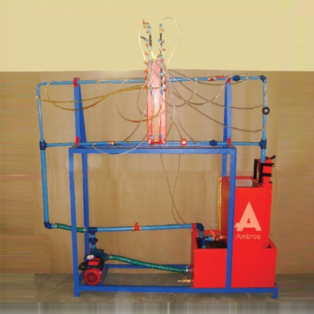
The Set-up consists of a ½ bend and elbow, a sudden expansion & sudden contraction fitting from 15 mm to 25 mm, ball valve and gate valve. Pressure tapings are provided at inlet and outlet of these fittings under test. A differential manometer fitted in the line gives pressure loss of individual fitting. Present Set-up is self-contained water re-circulating unit, provided with a sump tank and a centrifugal pump etc. Flow control valve and by-pass valve are fitted in water line to conduct the experiment on different flow rates. Flow rate of water is measured with the help of measuring tank and stop watch.
EXPERIMENTS:-
Ø To determine loss of head in the fitting at various water flow rates.
Ø To measure the loss co-efficient for the pipe fittings.
UTILITIES REQUIRED: –
Ø Water Supply and Drain
Ø Electricity Supply: Single Phase, 220 V AC, 0.5 kW.
TECHNICAL SPECIFICATION: –
Ø Sudden Enlargement : From 15 mm to 25 mm
Ø Sudden Contraction : From 25 mm to 15 mm
Ø Bend : ½
Ø Elbow : ½
Ø Ball Valve : ½
Ø Gate Valve : ½
Ø Water Circulation : FHP Pump, Crompton / Sharp make
Ø Flow Measurement : Using Measuring Tank with Piezometer, Capacity 25 Ltrs.
Ø Sump Tank : Capacity 50 Ltrs.
Ø Stop Watch : Electronic
Ø Control Panel : On / Off Switch, Mains Indicator etc.
The whole Set-up is well designed and arranged in a good quality painted Structure
Related products
Impact Of Jet On Vanes Apparatus
DESCRIPTION:-
The Set-up consists of two sided clear fabrication. Water is fed through a nozzle and discharged vertically to strike a target carried on a stem, which extends through the cover. A weight carrier is mounted on the upper end of the stem. The dead weight of the moving parts is counter balanced by a compression spring. The vertical force exerted on the target plate is measured by adding the weights supplied to the weight pan until the mark on the weight pan corresponds with the level gauge. A total of two targets are provided a flat plat and a hemispherical cup.EXPERIMENTS:-
Ø To measure the force developed by a jet of water impinging upon a different targets (Hemispherical & Flat Plate) and comparison with the forces predicted by the momentum theory.UTILITIES REQUIRED: –
Ø Water Supply & Drain Ø Electricity Supply: Single Phase, 220 VAC, 0.5 kWTECHNICAL SPECIFICATION: –
Ø Test Plates : Material Brass (2 Nos.) 1. Flat Plate 2. Hemispherical Cup Ø Nozzle : Material Brass Ø Stainless Steel Chamber : Having of opposite sides made of glass Ø Water Circulation : FHP Pump, Crompton / Sharp make Ø Flow Measurement : Using Measuring Tank with Piezometer,Capacity 40 Ltrs. Ø Sump Tank : Capacity 60 Ltrs. Ø Stop Watch : Electronic Ø Control Panel : On / Off Switch, Mains Indicator etc. Ø The whole Set-up is well designed and arranged in a good quality painted StructureOrfice Mouthpieces Apparatus
DESCRIPTION:
An orifice is an opening made in the side or bottom of tank, having a closed perimeter, through which the fluid may be discharged. A mouthpiece is short tube fitted to a same size circular opening provided in a tank so that fluid may be discharged through it. Orifice and mouthpiece are used to measure the rate of flow of liquid. The apparatus is designed to measure the co-efficient of discharge of orifice & mouthpiece. The apparatus consists of a supply tank, at the side of which a universal fixture for mounting orifice or mouthpiece is attached. A centrifugal pump supplied the water to supply tank. Head over the orifice/mouthpiece is controlled by a by pass valve provided at pump discharge. A measuring tank is provided to measure the discharge. A gauge for measuring X and Y co-ordinates of jet from the orifice is provided, which is used to calculate Cv of orifice.SPECIFICATIONS:
[1] Supply Tank – 0.4 X 0.3 X 0.5m height [2] Orifice – 8mm and 10 mm. [3] Mouthpiece (a) LID = 4 (b) L/D = 1 (c) Bordas mouthpiece. (d) Convergent mouthpiece. [4] X-Y gauge for orifice jet co-ordinates. [5] Measuring tank of suitable capacity OR a calibrated water flow meter. [6] Sump tank of suitable capacity. [7] 0.5 HP pump with valve. A technical manual accompanies the unit.SERVICES REQUIRED:
[1] Flow surface 2 mtrs. X 1 mtr. X 1.5 mtrs. height. [2] 230 Volts, 5 Amp. Stabilized AC. Power Supply.Reynold S Apparatus
DESCRIPTION:-
The Set-up is designed to verify Reynold’s Apparatus experimentally. The Apparatus consists of a glass tube which one end having bell mouth entrance connected to a water tank. At the other end of the glass tube a cock is provided to vary the rate of flow. Flow rate of water can be measured with the help of Measuring Cylinder and Stop Watch, supplied with the set-up. A capillary tube is introduced centrally in the bell mouth. To this tube dye is fed from a small container, placed at the top of Constant head Tank, through polythene tubing.EXPERIMENTS:-
Ø To study different types of flow. Ø To determine the Reynold’s Number and hence the type of floe either laminar or turbulent.UTILITIES REQUIRED: -
Ø Water Supply. Ø DrainTECHNICAL SPECIFICATION: - | ||
| Ø Tube | : | Material Borosilicate Glass |
| Ø Dye Vessel | : | Material SS, Suitable Capacity |
| Ø Capillary Tube | : | Material Copper/Stainless Steel |
| Ø Constant Head Water Tank | : | Capacity 40 Liters. |
| Ø Water Circulation | : | FHP Pump |
| Ø Flow Measurement | : | Using Measuring Cylinder |
| Ø Sump Tank | : | Capacity 60 Liters |
| Ø Stop Watch | : | Capacity 60 Liters. Electronic |
| Ø Control Panel Comprises of | : | Standard make, On/Off Switch, Mains Indicator, etc. |
| Ø The Whole set-up is well designed and arranged in a good quality painted structure. | ||










Reviews
There are no reviews yet.