[contact-form-7 404 "Not Found"]
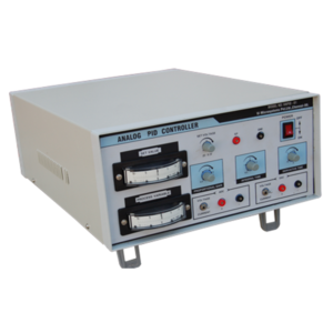
Analog PID Controller
The analog PID controller is a special purpose analog controller with operational amplifiers The controller permits a detailed analysis of the application of proportional, integral and derivative control to the improvement of their performance. The controller may be used at high speed for oscilloscope observation or at a low speed for meter observation.
FEATURES:
• Two analog meters (centre zero meters) to display the set variable and process variable. • In built regulated power supply. • Provision to vary and measure the setpoint (0-5)V • Provision to vary the proportional gain, Integral time and derivative gain. • Provision to give either (4-20)mA or (0-5)V externally as a process variable. • Provision to select the controller output as (4-20)mA or (0-5)V internally. • All the components are mounted in an attractive cabinet. • Interface with any realtime process (Level, Flow, Temperature, Pressure, DC motor speed control etc.,)DC Servo Motor Controller
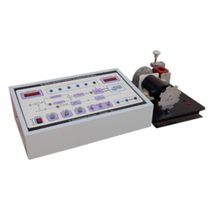
This trainer designed for versatile Applications / Experiments mentioned below. It consists of(i) a PWM Chopper Drive using MOSFET (ii) DC Servo Motor (iii) Speed Sensor (v) PI Loop for speed. This trainer system is a compact & advanced version for class room experiment setup for the students to operate and study a practical speed measurement using optical sensor and speed control system.
FEATURES:
• One 12V PMDC Motor mounted on a open frame. • Speed Range: 0 to 1500 RPM. • Speed Sensor fixed on the frame. - Photo interrupter with optical Encoders. • One F/V converter is provided to convert the pulses to voltage output. • Speed controller provided to select - Proportional circuit. - Proportional plus Integral circuit. • One 3½ digit display to display the speed of the DC Servo motor / set value. • A switch provided to select the reference or the actual speed. • All important signals are terminated at sockets. So that, the student can monitor / measure the signals using CRO, DVM, Frequency counter etc.Frequency Response Analysis of Lead Lag Network
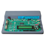
Frequency response of Lead, Lag network using P+I+D controller is a special purpose analog simulation, create using operational amplifiers. This simulator permits a detailed analysis of the first order and second order systems on the application of proportional, integral and derivative control to the improvement of their performance. The simulator may be used at high frequency for oscilloscope observation.
FEATURES:
• Built-in Function Generator (sine & square). • Self contained power supplies and power ON/OFF switch with indication. • Full mimic diagrams in the front panel. • The simulated process. - Simple Lag Process - Simple Lead Process • The simulated PID controller - Integral controller scaled in Integration time. - Derivative controller scaled in derivative action time. - Proportional band control scaled in % proportional band (PB).Process Control Simulator
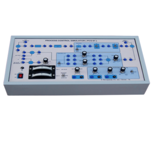
The process control simulator is a special purpose analog simulator with operational amplifiers The simulator permits a detailed analysis of the first order, second order and third order systems and the application of proportional, integral and derivative control to the improvement of their performance. The simulator may be used at high speed for oscilloscope observation or at a low speed for meter observation.
