[contact-form-7 404 "Not Found"]
Cam Analysis Apparatus
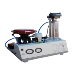
The apparatus is designed to study the cam profiles and performance of cam and follower system. The apparatus consists of a shaft supported by ball bearings upon which three different types of cams can be mounted.
The push rod for follower is supported vertically, which can adopt three different types of followers. Cams and followers can be changed easily. A variable speed motor rotates the cam. A dial gauge permits plotting of follower displacement with respect to cam position. By operating the system at different Speeds, jump speed can be found and also the effect of weight and spring force on jump speed can be studied. Jump can be visualized also with the help of stroboscope (it is not supplied With the product).
SPECIFICATIONS OF CAM ANALYSIS APPARATUS:
1.Cam -Eccentric, tangent and circular ARC type – one each. 2.Follower- mushroom, flat faced and roller type – one each. 3.Cams and followers are hardened to reduce wear of the surfaces. 4.Variable speed motor coupled to camshaft of suitable range and Variac. 5.A dial gauge to note the follower displacement. 6.A technical manual accompanies the equipment.SERVICES REQUIRE FOR CAM ANALYSIS APPARATUS:
1.230 V, A.C. stabilized supply along with earthing connection. 2.Bench area 0.5m x 0.5m x 0.5m height. 3.Tachometer to measure the jumping speed, (can be supplied extra)Coriollis Component Of Acceleration
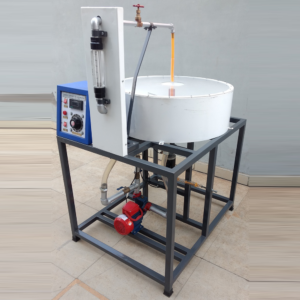
This set up is designed to study coriollis component of Acceleration of a slider crank Mechanism. The apparatus uses hydraulic analogy to represent the rotating slider. It consists of a rotating block with two arms in opposite direction. These tubes can be rotated at various speeds by using a swinging field motor, which also acts as a dynamometer to measure torque applied to rotating tubes. A Perspex window on top cover helps to visualize the process. Rotameter is used to measure water flow rate through tubes. Water is circulated by small monoblaock pump.
Specifications:
1.Main Tank with fiberglass lining. 2.Rotating Arms 9/6 mm dia, 300 mm long. 3.Motor – Swinging field, D.C., 0.5 HP. 4.Rotameter 5.Monoblock Pump 6.Control Panel comprising of – (i) Speed Control Unit. (ii) Speed Indicator. (iii) Necessary switches. 7.Rigid support frame.Range of Experiment:
Coriollis Component of Acceleration can be determined at various speeds of rotation and water flow rates.Service Required:
1.A.C. Single Phase .230 V. stabilized supply. 2.Floor Space -1.5 m X 1.5 m.Dead Weight Pressure Gauge Tester
DESCRIPTION:-
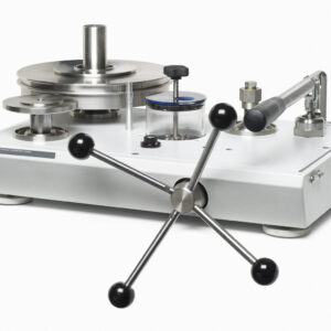
Dead weight Pressure Gauge Tester is manufactured to measure the Pressure gauge up to the capacity of 25kg/cm2.The system is nickled chrome to protect from rust. The weights are Zink Iron for long term use.EXPERIMENTS:-
• Study of the hydrostatic force on a plane surface under different submerged conditionsFEATURES:-
• Superb Painted structure • Simple to operate & maintainUTILITIES REQUIRED:-
• Machine Oil.SPECIFICATION:-
• Bourdon tube pressure gauge as manometer • Manometer with transparent scale • Manufactured from corrosion resistant materials • Components arranged on base plate. • Set of weights • Medium for transmitting pressure: hydraulicDrilling Tool Dynamometers
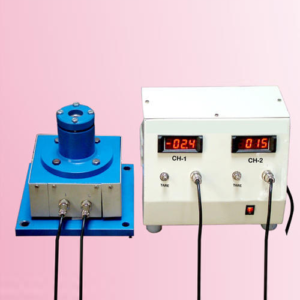
This is a armed wheel type strain gauge drill tool dynamometer designed to measure thrust and torque during drilling operation. This Dynamometer is suitable for drilling a hole up to 25mm size in mild steel. With this Dynamometer students can study the change in these force by varying speed, cut and feed
FEATURES:
1.Rigid in construction & Sensitive transuding and amplifying system for accuracy in force measurement. 2.Compact two channel digital force indicator. 3.Use of cutting fluid during operation is possibleSCOPE OF SUPPLY:
1.Mechanical sensing unit and work piece holder with strain gauges. 2.Control panel housing digital force indicator to measure both forces simultaneously, balancing potentiometer, connoting cables. 3.Necessary switches, fuses and screen printed front plate. 4.The dynamometer is calibrated at factory with help of proving ring and readings are directly in the from of kg.Epicyclic Gear Train Holding Torque Apparatus
It is a motorized unit consisting of SUN gear mounted on input shaft. Two plane gears mesh with the annular gear. These planet gears are mounted on a common arm to which output shaft is fitted. Loading arrangement is provided for loading the system and to measure Holding Torque.
Specifications:
1. External type Epicyclic Gear Train: a. Bearing blocks for input & output shafts. b. A gear train with Holding drum and handle. 2. Internal Type Epicyclic Gear Train: a. A compact Gear Train. b. Variable speed D.C. Motor c. Rope brake arrangement to measure output torque and holding torque. 3 Control Panel comprising of a. Digital Ammeter and Voltmeter. b. RPM Indicator. c. Speed Controller.Experimentation –
1. To measure epicyclical gear ratio between Input shaft and Output shaft. 2. To measure epicyclical gear ratio between Input shaft and holding drum. 3. To measure Input torque, Holding torque and Output torque.Service Required –
1. Floor Space – about 1.5m x 2m. 2. 230 V.AC stabilized power supply.Generation Of Involute Gear Tooth Profile
This board illustrates the process of cutting of involutes Gear Teeth, by use of rack type cutter It consists of 3 white acrylic discs A, B, C. having pitch circle diameter 450 mm, 300 mm & 200 mm respectively. A gear tooth profile with module 25mm can be traced out on a peace of paper placed between disc and cutter. An affect of Interference and Undercutting on correct profile of gear tooth can be studied from the profiles traced.
Grinder Tool Dynamometers
This a simple set up to study the various forces resolved during grinding operation, designed by sharp techno system for demonstration purpose for the students undergoing tool desing study. This unit works on octagonal ring method using strain gauge as a sensor. A two channel digital force indicator facilitates to measure both forces simulteniously.
FEATURES:
1.Rigid in construction & compact unit. 2.Assessment of cutting forces by giving due consideration to various parameters like depth of cut, material, speed and feed . 3.Eassy in handling & Digital force indicators to measure two forces simultaneously.SPECIFICATIONS:
1.Mechanical sencing unit with two octagonal rings and strain gauges. 2.Two channel digital force indicator with balancing potentiometers and polycarbonate front plate. 3.Range of force measurement in coordinate direction – 0 to 200 kg. 4.Over all size of mechanical unit – 300 x 300 mm.SERVICE REQUIRED:
1.Necessary surface grinding machine. 2.230 volts, single phase, 50 Hz stabilized power supply.Interference Undercutting
The board shows the demonstration of this phenomenon of Interference and Undercutting. When we rotate the teeth in anticlockwise direction, as the teeth is undercut is gives us a smooth working. When we give a rotation in clockwise direction, we can observe that the rack tip will be resisted by the tooth flank thus giving interference.
Journal Bearing Apparatus
DESCRIPTION:
The apparatus consists of a plain steel shaft encased in a bearing and directly driven by a small electric motor. The bearing is freely supported on the shaft and sealed at motor end. The motor speed is precisely controlled by control unit and sealed at motor end. The motor speed is precisely controlled by control unit and can be run in both directions. The bearing contains twelve equi-spaced pressures tapping around circumference and four along the axis. All are connected by light flexible plastic tube to the manometer so that the pressure head of all sixteen point can be observed at a time. The bearing can be loaded by attaching weight to the arm supported beneath it.SPECIFICATIONS:
1. Journal : 50 mm. dia. (nominal) 2. Bearing : 55 mm. dia. 3. Weights : 4 adjustable weights 4. Motor : D.C. shunt Motor, 3,000 RPM. 5. Control panel : For speed control of Motor 6. Manometer panel : 16 tube Manometer 7. Oil recommended : SAE 10EXPERIMENTS:
1. Observation of the pressure profile at various conditions of load and speed. 2. Plotting the Cartesian and polar pressure curves. 3. Plotting the theoretical Summerfield curves.SERVICE REQUIRED:
1. Electric Connections : A.C Single Phase, 230v. supply with ear thing. 2. Stand Alone Space : 1.5m X 1.5m X 4m Height.Lathe Tool Dynamometers
This is a strain gauge type two component lathe tool dynamometer designed to measure vertical and horizontal forces on the while orthogonal cutting process. The unit is in two parts one is mechanical sensing unit or tool holder, which can mounted on the top of the Ross slide after removing swivel base and compound slide of a lathe and digital force indicator. With this Dynamometer student can study the change in these forces by varying Speed, Cut and Feed.
FEATURES:
1.Rigid in construction 2.Sensitive transuding and amplifying system for accuracy in force measurement. 3.Compact Digital force indicator. 4.Use of cutting fluid during operation is possible.SCOPE OF SUPPLY:
1.Mechanical sensing unit or Tool Holder with string gauges. With H.S.S. tool of ½ “ size. 2.Control panel housing digital force indicator to measure two forces simuletensiously, balancing potentiometers, connoting cable. 3.Necessary switches, fuses and polycarbonate front plate. Range o to 500 Kg. 4.Centre Height, P.C.D.of clamping bolt size, clamping Bolt size. Three component lathe tool dynometer is also available.Milling Tool Dynamometers
This is a simple and essay to understand set up introduce by sharp techno systems to study the behavior of cutting forces during milling operation in three directions. With this unit students can evaluate cutting depth, speed and feed. The unit works on standard method of octagonal ring with strain gauges. It is in to part one mechanical rings sandwiched between two M.S. plate with strain gauges fixed on it. This set of octagonal rings transmits the relevant data to the force indicator during milling operation.
FEATURES
1.Rigid construction & Compact Unit. 2.Assessment of cutting forces by giving due consideration to various parameters like depth of cut, material, cut, material, speed and feed. 3.Eassy in handling & Digital force indicators to measure three forces simuleniously.SPECIFICATIONS-
1.Mechanical sencing unit with set of octagonal rings and strain gauges. 2.Three channel digital force indicator with balancing potentiometers and polycarbonate front plate. 3.Range of force measurement in coordinate direction – 0 to 500 kg. 4.Over all size of mechanical unit- 300 x 300 mm.SERVICE REQUIRED
1.Necessary Milling Machine with automatic feed arrangement and tooling 2.230 volts, single phase, 50 Hz stabilized power supply.Motorised Governor Apparatus
The unit consists of a base upon which the bearing holders and driving motor are bearing can be fitted in a holders to end conditions for test shafts, viz. Both end fixed and one end free, one end fixed. A Variac provided control of driving motor. The unit demonstrates the phenomenon of whirling of shafts with single rotor. As the test is destructive, after the test cannot be used, hence the unit only demonstrates the principle.
However, results obtained are closer to theory, as compared to those with bare shafts. Also, It can be demonstrated that, after passing whirling speed, shaft again starts running true.
