[contact-form-7 404 "Not Found"]
Citical Radius Of Insulating Material
Citical Radius of Insulating Material:
At particular radius of insulation over a cylinder, loss of heat is maximum. The unit consists of a G.I. pipe provided with plaster of Paris insulation on out side surface. Four pipes are provided with heater inside having input control. Input to heaters is measured by common voltmeter and ammeter, by controlling input to heaters, it is shown that critical radius of insulation is ratio of thermal conductivity and outside heat transfer co-efficient.
SPECIFICATIONS:
1.G. I. Pipes with electrical heater inside – 4 Nos. 2.Insulation over the pipes of different thickness. 3.Controls and Measurements – a) Dimmerstat to control heater input – 4 Nos. b) A voltmeter and ammeter to measure inputs to heater. c) Digital temperature indicator to measure temperatures across insulation. d) Necessary switches and controls. A technical manual accompanies the unit.SERVICES REQUIRED:
230 V, 5 Amp., A.C., Supply with earthing connection. Floor Area of 1 m. X 1 m X 1.5m. height.Composite Walls Apparatus
Composite Walls Apparatus:
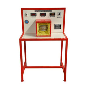
The apparatus consists of a pair of M.S. plates, Bakelite, brass/aluminum. These plates in series on either side of the heater form a composite wall. The whole unit is clamped in a frame, which can be viewed through the Perspex sheet. The thermocouple tapings enables us to find out the conductivity and resistance of the composite walls.
SPECIFICATIONS:
1.Heater- Mica healer of dia. 250 mm. 2.Plates- a) M.S. plates of thickness 25mm & dia. 250mm.-2 nos. b) Bakelite plates of thickness 10mm & dia. 250mm.-2 nos. c)Brass/Aluminum plates of thickness 15mm & dia. 250mm.-2nos 3.Dimmerstat – 2 A capacity. 4.Measurements — a) voltmeter and an Ammeter to measure input power. b) Multichannel digital temperature indicator to measure temperatures at- various points. A technical manual accompanies the unit.SERVICES REQUIRED:
230 V, A.C. stabilized supply along with earthing connection. Bench area Im x lm x 0.5m heightConcentric Tube Heat Exchanger
(A)Plain Tube ( Water To Water ):
The apparatus consists of two concentric tubes. Inner tube consists of copper tube through which hot water flows. While the outer tube consists of GI pipe through which cold water flows. The arrangement enables the parallel and counter flow of the cold water. The inlet and outlet temperatures and the flow measurement enable to find out the heat exchanged LMTD, and effectiveness of the equipment.
Specifications:
1.Inner copper tube I.D, 12.7mm. and outer G. I. Pipe I. D. 15mm. approx. and 1.5m. length. 2.Thermometers – 4 nos. 3.Measuring flask – 1 Lit. capacity. 4.Geyser-3 kW. Single phase.Services required
1.220v, 15A, stabilized single-phase AC supply. 2.Floor area – 3m x I m x 1 m height. (B) Finned Tube ( Water To Air ): The apparatus consists of two concentric tubes. Inner tube consists of copper tube through which hot water flows. It is finned at its outer diameter to increase the heat transfer surface. While the outer tube consists of GI pipe through which cold air flows. The arrangement enables the parallel and counter flow of the air. The inlet and outlet temperatures and the flow measurement enable to find out the heat exchanged LMTD, and effectiveness of the equipment.Specifications:
1.Inner copper tube I.D. 12.7mm. and outer G. I. Pipe I. D. 25mm. approx. and 1m. length. 2.Thermometers – 4 nos. 3.Orifice meter along with manometer. 4.Measuring flask – 1 Lit. Capacity. 5.Geyser-3 kW. Single phase.Services Required
1.220v, 15A, stabilized single-phase AC supply. 2.Floor area – 3m x 1m x 1m height.Critical Heat Flux Apparatus
The apparatus demonstrates the regimes of pool boiling. The test section consists of a test wire surrounded by water of constant temperature. The surface temperature of the test wire is heated by passing current through it. Due to the temperature difference between the wire surface and surroundings, the difference regimes are observed till the burnout point.
Specifications:
1.Test wire -35 gauge or 40 gauges. Length = 10cm. 2.Nichrome heater- 1 kw capacity – 1 nos. 3.Glass trough of sufficient capacity. 4.Table light to observe the test wire. 5.Voltmeter and ammeter to measure the input to the test wire. 6.Dimmerstat to adjust the voltage. A technical manual accompanies the unit.SERVICES REQUIRED:
1.220v, ISA, stabilized single-phase supply. 2.Floor surface- 1m x 1m at working height.Emissivity Measurement Apparatus
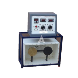
The apparatus consists of a test plate and a comparator. A black plate is used as a comparator for test plate. When all the physical, dimensions and the temperatures are equal, heat losses from both plates will also be the same, except radiation losses. Hence the input difference will be due to difference in emissive. Both the plates are kept in a panel enclose with perplex front and are given inputs through separate dimmerstats so that temperatures of both can be kept equal. Thus emissivity can determine over a wide range of temperatures.
SPECIFICATIONS:
1.Test plate and Black plates — 160mm. Dia. Aluminum plates, mounted in Panel with mica heater inside. 2.Instrumental panel consisting of- a)Voltmeter and ammeter for input measurement to both heaters through a selector switch. b)Separate dimmers for both the plates. c)Multichannel digital temperature indicator. A technical manual accompanies the unit.SERVICES REQUIRED:
1.Space area of 1.5m x 1 m. at working height. 2.230v, 15A, AC supply with earthing connectionForced Convection Apparatus
The unit consists of a circular pipe; loosing heat by forced convection to air, being forced through it. Constant heat flux is added to pipe by an electrical heater, provided with input control. The pipe surface temperature is measured at various points along length of pipe. Temperature of air at inlet and outlet of test section are measured. Thus the students can calculate local and overall heat transfer coefficients in forced convection, at various airflow rates and various heat flux values.
SPECIFICATIONS:
1.Test pipe – 32mm NB GI pipe, 500 mm. long, heated by band heater, outside. Centrifugal blower to force air through test pipe with How control valve. 2.Variac 2A, capacity to force air through test pipe with flow control valve. 3.An orifice meter with differential water manometer. 4.Voltmeter and Ammeter to measure heater input. 5.Multichannel digital temperature indicator to measures various temperatures. 6.A technical manual accompanies the unit.SERVICES REQUIRED:
1.Bench area of about 1m. x 0.75 m. at working height. 2.239v, 15A, AC, supply with earthing connection.Heat Pipe Apparatus
Heat Pipe Apparatus:
Heat pipe is an interesting device, which is used to transfer heat from one location to another.
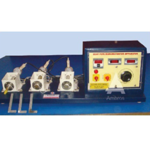
The apparatus consists of three pipes, viz. A heat pipe, copper pipe and stainless steel pipe. Ail the pipes have same physical dimensions. Copper and stainless steel pipes serve the purpose of comparison of heat pipe performance. All pipes are mounted vertically with a band heater at lower end and water filled heat sink at upper end. Nearly isothermal operation of heat pipe is clearly visualized from longitudinal temperature distribution of the pipe.
SPECIFICATIONS:
1.Heat pipe – Stainless Steel pipe, 25 mm O.D., 450 mm. Long. Sealed at both ends, evacuated and filled partially with distilled water – one No. 2.Copper and stainless steel pipe of same size as that of heat pipe – one each. 3.Equal capacity heater at bottom end of each pipe. 4.Water filled heat sinks at upper end of each pipe.Measurements and controls
a) Dimmerstat to control heat input to all the heaters – 4 amp. Capacity One No. b) A voltmeter and an ammeter to measure input to heaters One each. c) Multichannel digital temperature indictor to measure temperatures along the length of pipes.Four thermocouples are provided on each pipe. v Thermometers to note down water temperatures in heat sinks – 3 Nos.Services Required:
230 VA.C. Single Phase supply. Floor Area = 1 m X 0.5m X 0.5 m height.Heat Transfer In Aagitated Vessel
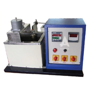
The unit consists of a vessel with class wool insulation ail around. A helical coil made of copper is fixed inside the vessel. A motorized agitator is fixed at the center of the coil. The vessel is provided with an electric heater and a controller is also provided for vessel. Heater heats water in the jacket while cold water is circulated through coll. Temperature of circulated water and water In vessel Is measured and thus heat transfer coefficient at various agitator speeds can be determined.
SPECIFICATIONS:
1.Vessel approx. 20 lit. capacity, provided with glass wool insulation all around and electric heater at the bottom. 2.Agitator 150 mm dia, with 1/8 HP motor to drive the agitator. 3.Helical coil – 200 dia, 8 turns, made of 3/8″ dia. copper tube. 4.Controllers for heater and agitator motor. 5.Temp. Indicator for vessel water temperature and circulated water inlet and outlet.SERVICES REQUIRED:
1.Single phase 230V, 15 A stabilized supply. 2.Water flow at the rate of 4 to 5 lit. per min. 3.Suitable drain arrangement for water. 4.Floor area -1.5 mtr. X 1 mtr. X 1 mir height.Lagged Pipe Apparatus
Lagged Pipe Apparatus:
The apparatus consists of three concentric pipes mounted on suitable stand. The space between innermost and the middle pipe is fifed with a lagging material and the space between the middle and the outer most is filled with and other lagging material. The lagged pipe is heated with a cartridge heater inserted at the axle length of the pipe. Voltmeter and ammeter on the panel can measure the input to the heater. The intermediate temperatures can be measured by the thermocouples attached at the surfaces of the pipe. Thus the resultant conductivity of the materials can be found out.
SPECIFICATIONS:
1.Pipes : a)Gl pipe (innermost) – 6 cm. (Outer Diameter). b) Gl Pipe (Middle) – 8.5 cm. (Mean Diameter) c)G! Pipe (Outermost) – 10.7 cm. (inner Diameter) d)Length of pipes 1 Meter. 2.Heater : Nichrome wire cartridge heater placed centrally, of suitable capacity. 3.Control Panel : a)Single Phase Dimmerstat – 1 No. b)Voltmeter (0 – 250V) – 1 No. c)Ammeter (0- 2A) – 1 No. 4.Temperature Indicator : Multichannel Digital Temperature Indicator ranging (0 – 300 C) using Cr/AI ThermocouplesServices Required:
1. A.C. Single Phase 230 V electric supply 2. Floor Area-1.5 Meter X 1 Meter X 0.5 Meter HighNatural Convection Apparatus
The unit consists of a vertical brass pipe heated by a cartridge heater inside it. The pipe looses heat to atmosphere by natural convection. It is fitted in an enclosure to provide undisturbed natural convection currents. Thermocouples are attached on the pipe to measure local temperatures. Heater input is measured on voltmeter and ammeter. Thus students can determine overall heat transfer coefficient and local transfer coefficients in natural convection at various heat transfer rates.
SPECIFICATIONS:
1.Pipe – Brass pipe, 38mm. dia. (OD) 500mm. long, fitted with cartridge heater inside. 2.Thermocouples are fitted along with the length of pipe for Temperature measurement – 7 nos. 3.Enclosure 200mm. x 200mm. x 800mm. size, with one side of Perspex sheet. 4.Measurements & Controls a) A Dimmerstat for heater input control. b) Voltmeter and Ammeter for heater input measurement. c) Multichannel digital temperature indicator. A technical manual accompanies the unit.SERVICES REQUIRED:
1.Bench area of 1.5m x 0,75m. at working height. 2.230v, 5A, AC, electric supply with earthing connection.Pin Fin Appatatus
The apparatus consists of a channel in which the pin fin is tested in both natural as well as forced convection. The channel is connected to the suction of blower. The blower is operated to touch the pin fin in forced convection only. In natural convection, the window above the pin fin is kept open to the atmosphere. Five thermocouple tapings are given along the length of the fin. Thus the temperature distribution along the length can be distinguished. Also natural and forced heat transfer co-efficient, effectiveness, etc. can be found out.
Specifications:
1.Three pin fins- a) M. S. b) Brass c) Al 2.Channel- 150mm x 100mm x 1000mm 3.Blower – run by f.h.p. motor. 4.Orifice meter along with water manometer to measure airflow. 5.Voltmeter and ammeter to measure power input. 6.Cr- Al thermocouple with 6 tapings along with temperature indicator. 7.Dimmerstat to control power input. 8.A band heater to heat the pin fin. A technical manual accompanies the unit.Services required:
1.220v, stabilized single phase supply along with earthing Connection. 2.Floor area 2m x 1m x 1m height.Plate Type Heat Exchanger Apparatus
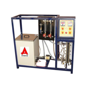
The unit consists of a plate type heat exchanger, in which cold fluid is cold water and hot fluid is hot water, which is obtained from geyser. The inlet and outer connections of the fluids are positioned so as to make the exchanger counter flow type. Hot and cold fluids pass between alternate plates various measurements provided enables the students to determine heat transfer rate, LMTD, heat transfer coefficients and effectiveness of the heat exchanger.
