[contact-form-7 404 "Not Found"]
Centrifugal Blower Test Rig
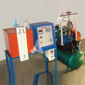
The apparatus consists of a spiral casing, which houses an impeller. Impeller is driven by a variable speed D.C. motor. Three, interchangeable impellers, viz. Radial forward and Backward curved vanes are provided with the unit. Digital indicators are provided for speed of impeller. A venture provided measures the discharge. Thus students can evaluate the performance of different impellers at various speeds.
SPECIFICATIONS:
1.Blower – Spiral casing with three interchangeable impellers viz. forward, backward and radial vanes. 2.Drive Motor-1 HP DC motor, 3000 RPM with Dimmer control to vary the speed from 300 to 3000 RPM. 3.Digital Speed indicator for speed measurement. 4.Ventura with water manometer to measure air flow. 5.Water manometer to measure discharge pressure. 6.Discharge pipe with flow control valve. 7.A technical manual accompanies the unit.SERVICES REQUIRED:
1.Floor space of about 2m X 1.5m X 1.5m height. 2.230 V. 5A., 50 Hz, AC Supply.Digital Bomb Calorimeter
DIGITAL BOMB CALORIMETER
Bomb Calorimeter outfit provides a simple and inexpensive method for determination of heat of combustion of organic matter and the calorific value and sulphur content of solid and liquid fuel. The outfit supplied is complete for analysis as per the method recommended by British Standard Institution BS 1016. All parts of the outfit have been finished of petroleum and British Standard Institute.SUPPLIED WITH
Calorimeter Vessel with bomb support, Water jacket, Combined Lid for calorimeter vessel and water jacket, Stirrer, Connecting Leads, Connecting tube to connect bomb & pressure gauge, Connecting tube with fine adjustment valve, to connect pressure gauge, pressure gauge on stand, Spanner for oxygen tube connection, Ignition Wire, (2 meters) Nichrome, Cotton Real, stand for bomb lid, Hook for lifting bomb, stainless steel Crucible, Gelatine capsules, Gas release valve, Bomb firing unit, Vibrator, Timer, Benzonic acids. ‘O’ Ring Big, ‘O’ Ring Small, ‘O’ Ring for Stirrer Valve for Bomb, Valve Kay. Complete with Instruction manual.Electropneumatic Training
LIST OF EXPERIMENTS
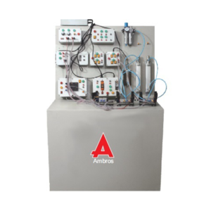
1.Intoduction of Relay and Contactor. 2.Introduction of Proximity Sensor, Capacitive & Photoelectric Sensor, Limit Switch. 3.Introduction to Pressure Switch, Electrical Counter, ON Timer & OFF Timer. 4.Operation of single acting cylinder with single sol. valve and single limit switch. 5.Operation of double acting cylinder with single sol. valve and single limit switch. 6.Continuous operation of double acting cylinder with single solenoid valve and two limit switches. 7.Operation of double acting cylinder with single solenoid valve, AND gate of electrical switches. 8.Operation of double acting cylinder with single solenoid valve, OR gate of electrical switches. 9.Operation of double acting cylinder with single solenoid valve, NOR gate of electrical switches. 10.Operation of double acting cylinder with single solenoid valve, NAND gate of electrical switches. 11.Operation of double acting cylinder with double solenoid valve. 12.System pressure will be maintained in specified pressure limit with pressure switch. 13.Operation of double acting cylinder with single solenoid valve with ON time delay. 14.Operation of double acting cylinder with single solenoid valve with OFF time delay. 15.Continuous operation of double acting cylinder with specified no. of cycles using Counter. 16.Sequencing of Two Cylinders. Cycle is Cylinder A Extends, Cylinder B Extends, Both Cylinder retracts simultaneously. A+, B+, (A-, B-). , Sequencing of Two Cylinders. Cycle is Cylinder A Extends, Cylinder B Extends, Cylinder A retracts then Cylinder B retracts. A+, B+, A-, B-SALIENT FEATURES
1.Self combined mobile unit. 2.Only electrical supply required. 3.All the components are easily accessible. 4.Real life components of reputed manufacturers provided. 5.Quick connections possible due to special fittings/pipes. 6.Tried and tested components and circuits. 7.Specially designed electrical control panel enabling students to develop their own electrical circuits. 8.Completely user friendly and highly interactive software provided with PC based Trainer. 9.Modular design with facilities to operate simple mechanisms. 10.Pneumatically operated models available as additional supply. 11.Training of Trainers offered at regular intervals. 12.Two years performance guarantee for any manufacturing defects.Hydraulic Trainer Classic
Silent Features:
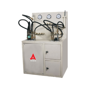
1. We are manufacturing cylinders for industrial applications. Our cylinders can withstand pressure up to 160 Bar. 2. Mobile and self-contained unit, only electrical connections are required. 3. Simplicity of operation and designed for amateur use. 4. Two pressure relief valves are provided in the system. One is provided inside the tank to increase the safety. 5. Hoses can withstand pressure of 188 Bar. 6. Test Pressure : 80 Bar ; Operating Pressure : 40 Bar. 7. Realistic Industrial circuits are demonstrated. 8. Special Bell housing is provided to maintain the Run out between Pump and Motor below 0.020mm. 9. Special fixtures used for pipe bending and ferrule fitting arrangement. 10. Specially designed front mounting plate. 11. System is flushed with very high velocity (4 times the working pressure) byseparate oil which maintains class A cleanliness of system. 12. Lowest pressure drop in the system to avoid overheating. 13. Cylinder are manufactured from precision honed tubes, hardened ground, hard chrome plated piston rods and imported quality seals.Hydraulic Trainer Electrohydraulic
Silent Features:
1. software for simulation of Hydraulic circuits. 2. We are manufacturing cylinders for industrial applications. Our cylinders can withstand pressure up to 160 Bar. 3. Mobile and self-contained unit, only electrical connections are required. 4. Simplicity of operation and designed for amateur use. 5. Two pressure relief valves are provided in the system. One is provided inside the tank to increase the safety. 6. Hoses can withstand pressure of 188 Bar. 7. Test Pressure : 80 Bar ; Operating Pressure : 40 Bar. 8. Realistic Industrial circuits are demonstrated. 9. Special Bell housing is provided to maintain the Run out between Pump and Motor below 0.020mm. 10. Special fixtures used for pipe bending and ferrule fitting arrangement. 11. Specially designed front mounting plate. 12. System is flushed with very high velocity (4 times the working pressure) by separate oil which maintains class A cleanliness of system. 13. Lowest pressure drop in the system to avoid overheating. 14. Cylinder are manufactured from precision honed tubes, hardened ground, hard chrome plated piston rods and imported quality sealsOpen Wind Tunnel Apparatus
Technical Description
A wind tunnel is the classic experiment system for aerodynamic flow experiments. The model being studied remains at rest while the flow medium is set in motion, and thus the desired flow around the model is generated. Open wind tunnel used to demonstrate and measure the aerodynamic properties of various models. For this purpose, air is drawn in from the environment and accelerated. The air flows around a model, such as an aerofoil, in a measuring section. The air is then decelerated in a diffuser and pumped back into the open by a fan. The carefully designed nozzle contour and a flow straightener ensure a uniform velocity distribution with little turbulence in the closed measuring section. The flow cross section of the measuring section is square. The built-in axial fan with guide vane and a variable-speed drive is characterised by an energy-efficient operation at high efficiency. Air velocities of up to 28m/s can be reached in this open wind tunnel. The trainer is equipped with an electronic two-component force sensor.Lift and drag are detected and displayed digitally. The air velocity in the measuring section is displayed on the inclined tube manometer. The tube manometers is recommended for measuring the pressure curves in drag bodies. Extensive accessories allow a variety of experiments, for example lift measurements, pressure distributions, boundary layer analysis or visualisation of streamlines. The well-structured instructional material sets out the fundamentals and provides a step-by-step guide through the experiments.Learning Objectives & Experiments
– Determine drag and lift coefficients for different models – Pressure distribution when flowing around drag bodies – Boundary layer analysis – Investigation of flutter – Wake measurementFeatures
* Open wind tunnel for a variety of aerodynamic experiments * Homogeneous flow through the flow straightener and special nozzle contour * Transparent measuring sectionPneumatic Trainer Basic
LIST OF EXPERIMENTS
1.Operation of a Single Acting Cylinder 2.Speed Control Of Single Acting Cylinder 3.Operation of a Single Acting Cylinder with And Gate 4.Operation of Pneumatic Motor 5.Speed Control of Pneumatic Motor 6.Operation of D/A Cylinder with 5/3 Way Lever Operated DC Valve 7.Speed Control of D/A Cylinder with Flow Control (Meter In) 8.Speed Control of D/A Cylinder with Flow Control (Meter Out) 9.Speed Control of D/A Cylinder with Flow Control in Forward & Return Stroke 10.Sequencing of Motor & Double Acting Cylinder 11.Sequencing of D/A Cylinder with Single Acting Cylinder 12.Operation of Single Acting Cylinder with 5/2 Way Single Solenoid 13.Operation of Double Acting Cylinder with 5/2 Way Single SolenoidSALIENT FEATURES
1.Mobile self contained unit. 2.Simplicity of operation and designed for immature use. 3.Industrial components and circuits are demonstrated in the circuit. 4.Pneumatic valves of Shrader / Festo/ SMC or equivalent only. 5.Performance Guarantee of two years for any manufacturing defect. 6.Modular design with fitment of component at any corner of trainer. 7.Specially designed quick coupling.Rotary Air Compressor Test Rig
The Apparatus consists of a rotary vane compressor driven by an electric motor; Air intake is measured by an orifice meter and manometer, Discharge “pressure is measured by a pressure gauge. Power input of the compressor measured by an Energymeter. Thus the students can determine volumetric efficiency, power consumption and free air discharge of compressor.
SPECIFICATIONS:
1.Vane compressor – Rotary compressor, driven by 3 HP motor. 2.Calibrated orifice meter with water manometer to measure air intake. 3.Energy meter to measure input of the meter. 4.Pressure gauge to measure discharge pressure. 5.Control valve at delivery side. 6.Stop clock. 7.A technical manual accompanies the unit.SERVICES REQUIRED:
1.Floor space of approx. 1.5 X 1.5 m. X 1.5 M. height. 2.440V, 16A, 3ph. supply. 3.Tachometer.Separating Throttling Calorimeter
AIM
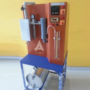
To find out dryness fraction of steam by combined separating and throttling calorimeter.
PRODUCT DETAILS
The steam passing out from separating calorimeter may still contain some water vapour , in it . in other words it may not be absolutely dry . again , in a throttling calorimeter steam after passing through the throttle valve must be superheated or at least dry saturated . this limits the extent of dryness fraction that can be reliably measured , depend up on the pressure of steam in the main steam pipe . if a sample of steam, which may be still wet after passing through the throttle valve i.e it will not be superheated . thus under this condition the throttling calorimeter fails to enable us in determining the value of dryness fraction of steam . to overcome this difficulties we make use of separating and throttling calorimeter . first the steam is passed through separating calorimeter where itlosses most of it’s moisture and becomes comparatively drier, it is than passed through the throttling calorimeter where super heating takes place with out changr of total heat . the temperature and pressure of steam after throttling are measured by using a thermometer and manometer respectively.DESCRIPTION
The set up consist of a separating and throttling calorimeter . a steam generator is provided at the base of the apparatus . a thermostat knob is provided at the front of apparatus to control the temperature inside the steam generator . steam from steam generator is passed from separating calorimeter where most of the water partical get separated from steam and then passed to throttling calorimeter where steam get superheated . after that superheated steam passed through heat exchanger to condense the steam.SAPARATING CALORIMETER
It consist of two concentric chamber , the inner chamber ,and the outer chamber . which communicates with each other through an opening at the top. As the steam discharge through the metal baskets ,which has a large number of holes , the water partical due to there heavier momentum get separated from the steam and collected in the chamber. The comparatively dry steam in the inner chamber moves up and than down aging through the annular space between the two chambers and enters the throttling calorimeter .THROTTLING CALORIMETER
It consist a narrow throat . pressure and temperature are measured by manometer and thermometer . the steam after throttling process passed through the heat exchanger and condensate is collected .UTILITIES REQURIED
1.WATER SUPPLY 3 lit/min (approx) 2.Drain 3.Electric supply : 1phase , 220 V A.C , 2Amp. 4.Steam table for calculation 5.Space required : 1.0 m X 1.0 mSingle Stage Air Compressor Test Rig
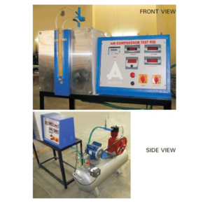
The test rig comprises of a Single stage air compressor fitted with an air tank with orifice, pressure gauges, and an energy meter to measure the input & a Temperature indicator measures the temperatures at various points. The compressor is mounted on air receiver along with the motor, and is provided with air relief valve (safety) and a pressure switch. The unit determines volumetric efficiency and isothermal efficiency at various discharge pressures
SPECIFICATIONS:
1.Air compressor – Single cylinder, Single stage type driven by a 2 hp. Three phase motor mounted on air receiver provided with delivery valve. 2.Air tank and orifice with water manometer for air intake measurement. 3.Pressure gauge to measure the discharge pressure. 4.Digital temperature indicator. 5.Energy meter to measure input power. 6.A technical manual accompanies the equipments .SERVICES REQUIRED:
1.Floor space of 2.5 X 1,5m. 2.440 V, 15A, 3ph. AC supply with neutral and earthing connection. 3.A hand tachometer.Steam Power Plant Trainer
Introduction:
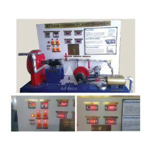
Steam Power Plant Working Unit – This Unit Helps The Students To Understand The Complete System Of A Thermal Power Plat. 1.Heat Energy Converts Water Into Steam 2.Steam Pressure When Moves A Engine Or Turbine Produces Mechanical Energy 3.Finally Mechanical Energy Is Converted Into Electricity Through AlternatorParts Details Of Boiler:
1.Boiler — For The Generation Of Steam We Have Provided Electrically Heated Boiler. 2.Diameter Of Boiler – 400 mm 3.Length Of Boiler – 600 mm 4.Heater 2 Pcs. – 3 KW (Each)Thin Cylinder Apparatus
A heavy bench top unit for studying the stress and strain in a thin walled cylinder under internal pressure. A thin walled cylinder is mounted between two support blocks. Internal pistons and seals create oil sealing. A handwheel at one end of the apparatus enables the cylinder end conditions to be adjusted to either open or closed. The internal pressure is adjusted by means of a hydraulic hand pump on the apparatus. An analogue pressure gauge displays the internal pressure whilst a pressure transducer gives feedback to the Data Acquisition Interface and Software supplied. Strain gauges are arranged on the external surface of the cylinder to measure the radial and circumferential surface strain. The strain gauges are at various angles.
