This apparatus is an effective demonstration of how the earth wire and fuse act together to protect both the user and the appliance.
When the appliance is connected correctly and the LEDs in the appliance will illuminate to show the appliance is working.
A fault is then demonstrated by swapping the live wire from inside the appliance to the case to show either the fuse melts (protecting the user and appliance) or in the case of no earth wire, the LEDs illuminate to indicate the passage of current through the person to ground.
The fuse is easily visible and can be seen to ‘blow’ when a fault occurs.The unit is supplied with 10 m of fuse wire and full instructions.
A 12 V DC power supply is required.
Connections are made via 4 mm shrouded sockets.
Comprising 1 welding coil of 5 turns on former with insulated handle and short-circuiting pins,1 annular melting trough with insulated handle to show heating by induction,1 jumping ring which is thrown clear when primary current is started and a floating ring which remains freely suspended when primary current is flowing.
For Westminster Electromagnetic Kit giving 1 V full wave rectified DC and 1 V / 2 V AC outputs at 8 A max.
The circuit diagram is printed on the top panel which also carries mains switch, light indicator and output sockets for DC and AC With 1.5 meter mains detachable cable.
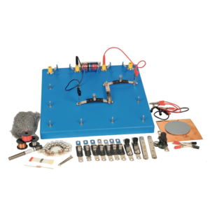
Enables students to investigate nature and properties of electricity by using simple circuits which are easily constructed on a base board.
The connector system uses P.C.B. strips with cut-out sections whose ends can easily be inserted in spring terminals, ensuring low contact resistance and ease of connection.
The kit consists of :
1. Baseboard, plastic, with spring terminals and three battery holders. (1)
2. Batteries. (3)
3. Lamps 1.25 V MES. (10)
4. Lamp holders mounted on PCB connectors. (6)
5. Plain connector PCBs. (10)
6. Wire wound potentiometer with crocodile clip connections. (1)
7. Silicon diode. (1)
8. Resistor 3.9 ohm 2.5 W (1)
9. Pair Leads, red, with crocodile clip at each end. (1)
10. Pair Leads, black, with crocodile clip at each end (1)
11. Pair Leads, yellow, with crocodile clips at each end. (1)
12. Switches mounted on PCB. connectors (2)
13. PVC rod 15 cm long (1)
14. Soft iron nails, 5 cm long (2)
15. Bare copper wire, swg 20 (2 m)
16. Bare eureka wire, swg 34 (2 m)
17. Plastic covered copper wire (2 m)
18. Electrode support (1)
19. Pencil lead electrodes (10)
20. Sheet copper foil, 150 mm square (1)
21. Pack Steel wool (1)
22. Instruction manual in English. (1)
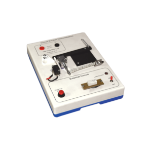
Investigate the working principle of circuit breaker type fuse with this demonstration model.
The apparatus is built on a robust plastic base and includes resistive loads to simulate external wiring circuits.
Applications of the thermal response of bimetal strips and also electromagnetism (movement from a solenoid) are clearly demonstrated in this model.
When a 12 V DC supply is connected (not supplied) the LED lights to show that current is flowing in the external circuit and the bi-metal strip can be seen to bend as its heater coil raises the temperature.
After a few minutes the bending is sufficient to trip the mechanism and the current path is broken.
At any current selection a short circuit situation can be initiated by pressing the red button and this produces an immediate response from the solenoid to disconnect the supply.
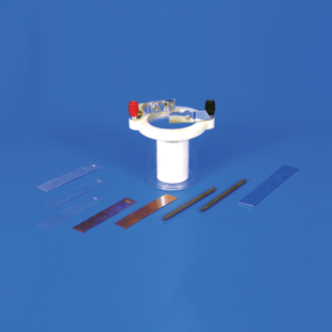
To demonstrate the characteristics of simple and primary cells.
Consists of a plastic jar with a screw-on plastic rim containing two adjustable brass electrode holders, eight electrodes of different metals and a porous ceramic cup.
With Instructions.
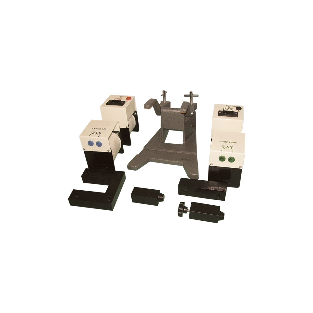
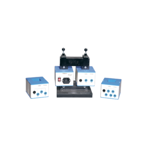
This heavy duty demountable transformer can be used for the study of transformertheory and many other alternating current phenomena.
This kit consists of:
1. A magnetic circuit made of highly permeable U shape metal sheet, which can be closed using two clamps with tightening screws.
2. Section: 40 x 40 mm with 150 mm length and 170 mm height.
3. One coil of 6000 turns with maximum current of 0.2 A. Intermediary coil of 2000 turns output.
4. One coil of 600 turns with maximum current of 2.5 A, which is mainly used to create the primary of transformer.
5. One coil of 1200 turns with maximum current of 1.25 A, fitted with intermediary 400 and 800 turns outputs.
6. One coil of 72 turns with maximum current of 12 A, fitted with intermediary 6, 30, 54 and 66 turns outputs.
7. Power supply cable.
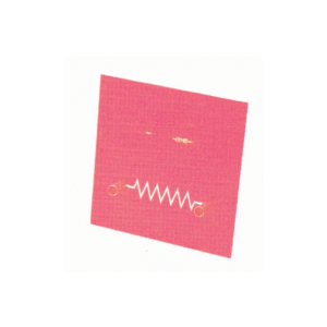
Designed to demonstrate to implement and applications of electrical, electronic devices and simple circuits. These modules are fitted with 4 mm sockets.
Components are directly mounted on printed PCB with diagram.Various modules are available as following Resistor
LDR
LED
Push Switch
Motor
Reed Relay
Reed Switch
Relay Nand Gate
Buzzer
Thermistor
Lamp Holder
Single Pole Double Throw Switch
Electromagnet
Power Transistor


































Reviews
There are no reviews yet.