A simple kit for students to gain insight into field poles, armatures and switches, one mounting base, two coils of insulated wire , field pole, mounting bracket, two armature halves, one piece of insulating tubing, motor shaft, two commutator insulators, two bronze wire brushes, two shaft supports, four paper fasteners, a AA battery holder and 6 each of screws and nuts.
Requires one AA battery, not supplied, with assembly instructions.
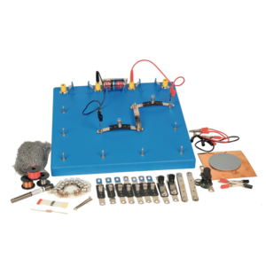
Enables students to investigate nature and properties of electricity by using simple circuits which are easily constructed on a base board.
The connector system uses P.C.B. strips with cut-out sections whose ends can easily be inserted in spring terminals, ensuring low contact resistance and ease of connection.
The kit consists of :
1. Baseboard, plastic, with spring terminals and three battery holders. (1)
2. Batteries. (3)
3. Lamps 1.25 V MES. (10)
4. Lamp holders mounted on PCB connectors. (6)
5. Plain connector PCBs. (10)
6. Wire wound potentiometer with crocodile clip connections. (1)
7. Silicon diode. (1)
8. Resistor 3.9 ohm 2.5 W (1)
9. Pair Leads, red, with crocodile clip at each end. (1)
10. Pair Leads, black, with crocodile clip at each end (1)
11. Pair Leads, yellow, with crocodile clips at each end. (1)
12. Switches mounted on PCB. connectors (2)
13. PVC rod 15 cm long (1)
14. Soft iron nails, 5 cm long (2)
15. Bare copper wire, swg 20 (2 m)
16. Bare eureka wire, swg 34 (2 m)
17. Plastic covered copper wire (2 m)
18. Electrode support (1)
19. Pencil lead electrodes (10)
20. Sheet copper foil, 150 mm square (1)
21. Pack Steel wool (1)
22. Instruction manual in English. (1)
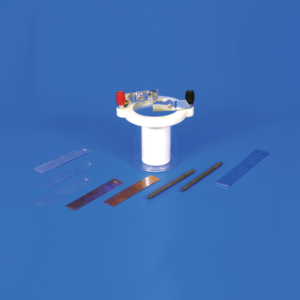
To demonstrate the characteristics of simple and primary cells.
Consists of a plastic jar with a screw-on plastic rim containing two adjustable brass electrode holders, eight electrodes of different metals and a porous ceramic cup.
With Instructions.
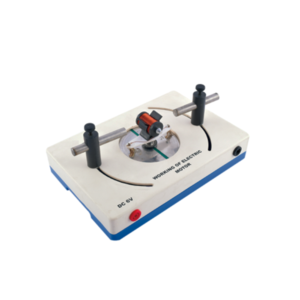
With this simple electric motor model students can investigate the relationship between voltage supplied to rotor and polarity / position of magnets.
On applying 6V DC to 4mm sockets, the rotor will begin to rotate across its vertical axis.
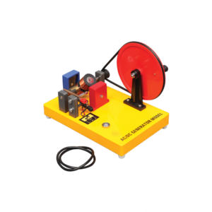
Generates both AC and DC.
When the two brushes of the generator are put in the two ends of the commutator, the output is an AC.
When the brushes are put in the middle of the commutator, the output is a DC.
Includes Instructions.
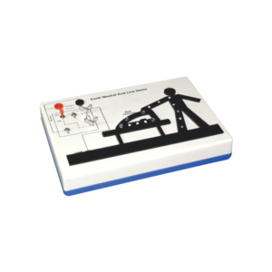
This apparatus is an effective demonstration of how the earth wire and fuse act together to protect both the user and the appliance.
When the appliance is connected correctly and the LEDs in the appliance will illuminate to show the appliance is working.
A fault is then demonstrated by swapping the live wire from inside the appliance to the case to show either the fuse melts (protecting the user and appliance) or in the case of no earth wire, the LEDs illuminate to indicate the passage of current through the person to ground.
The fuse is easily visible and can be seen to ‘blow’ when a fault occurs.The unit is supplied with 10 m of fuse wire and full instructions.
A 12 V DC power supply is required.
Connections are made via 4 mm shrouded sockets.




































Reviews
There are no reviews yet.