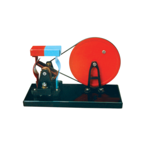
The dynamo model is mounted on a base with a driving wheel.
Output is through 4 mm sockets and a low voltage bulb is also provided as a simple output indicator.
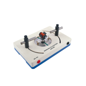
With this simple electric motor model students can investigate the relationship between voltage supplied to rotor and polarity / position of magnets.
On applying 6V DC to 4mm sockets, the rotor will begin to rotate across its vertical axis.
A simple form of D.C. motor with 2 pole armature wound with insulated copper wire and a permanent magnetic field provided by a removable bar magnet with a commutator and phosphor bronze brushes connected to 4 mm sockets, open construction, all parts visible.
For Westminster Electromagnetic Kit giving 1 V full wave rectified DC and 1 V / 2 V AC outputs at 8 A max.
The circuit diagram is printed on the top panel which also carries mains switch, light indicator and output sockets for DC and AC With 1.5 meter mains detachable cable.
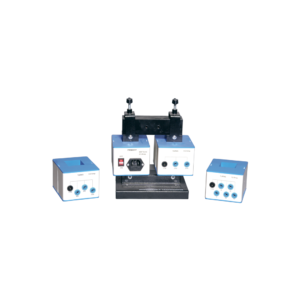
This heavy duty demountable transformer can be used for the study of transformertheory and many other alternating current phenomena.
This kit consists of:
1. A magnetic circuit made of highly permeable U shape metal sheet, which can be closed using two clamps with tightening screws.
2. Section: 40 x 40 mm with 150 mm length and 170 mm height.
3. One coil of 6000 turns with maximum current of 0.2 A. Intermediary coil of 2000 turns output.
4. One coil of 600 turns with maximum current of 2.5 A, which is mainly used to create the primary of transformer.
5. One coil of 1200 turns with maximum current of 1.25 A, fitted with intermediary 400 and 800 turns outputs.
6. One coil of 72 turns with maximum current of 12 A, fitted with intermediary 6, 30, 54 and 66 turns outputs.
7. Power supply cable.
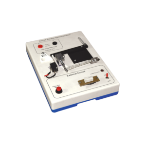
Investigate the working principle of circuit breaker type fuse with this demonstration model.
The apparatus is built on a robust plastic base and includes resistive loads to simulate external wiring circuits.
Applications of the thermal response of bimetal strips and also electromagnetism (movement from a solenoid) are clearly demonstrated in this model.
When a 12 V DC supply is connected (not supplied) the LED lights to show that current is flowing in the external circuit and the bi-metal strip can be seen to bend as its heater coil raises the temperature.
After a few minutes the bending is sufficient to trip the mechanism and the current path is broken.
At any current selection a short circuit situation can be initiated by pressing the red button and this produces an immediate response from the solenoid to disconnect the supply.
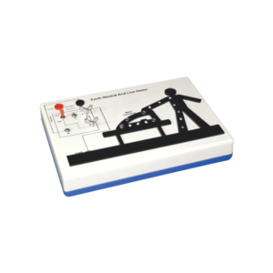
This apparatus is an effective demonstration of how the earth wire and fuse act together to protect both the user and the appliance.
When the appliance is connected correctly and the LEDs in the appliance will illuminate to show the appliance is working.
A fault is then demonstrated by swapping the live wire from inside the appliance to the case to show either the fuse melts (protecting the user and appliance) or in the case of no earth wire, the LEDs illuminate to indicate the passage of current through the person to ground.
The fuse is easily visible and can be seen to ‘blow’ when a fault occurs.The unit is supplied with 10 m of fuse wire and full instructions.
A 12 V DC power supply is required.
Connections are made via 4 mm shrouded sockets.



































Reviews
There are no reviews yet.