Students can explore how a simple electric motor works by doing a series of investigations.
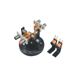
This St. Louis motor can be adjusted so students can study the effect of voltage and position of the brushes on the commutator.
The motor consists of a two pole DC armature. The brush holder, with two heavy binding post terminals, can be rotated for experiments.
The permanent bar magnets, supported by clamps, can be adjusted to the desired location.
This apparatus requires 4 D cell batteries with holder (not included) or a power supply and two connecting leads (not included).
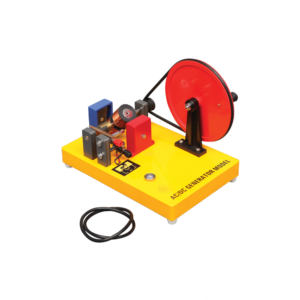
With driving wheel, to generate current, mounted on polished wood base with driving wheel in vertical position, a lamp holder and a lamp.
Output DC Current
Output both DC and AC current
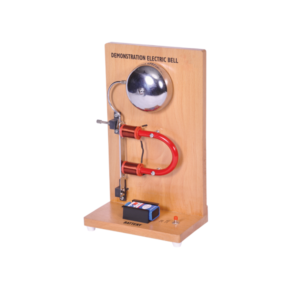
The large size of this battery operated apparatus allows students to better understand the operation of this basic circuit.
Works on 9 V Battery.
Includes Instructions.
On wooden stand.
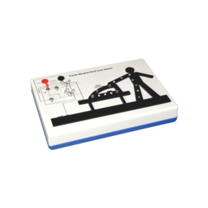
This apparatus is an effective demonstration of how the earth wire and fuse act together to protect both the user and the appliance.
When the appliance is connected correctly and the LEDs in the appliance will illuminate to show the appliance is working.
A fault is then demonstrated by swapping the live wire from inside the appliance to the case to show either the fuse melts (protecting the user and appliance) or in the case of no earth wire, the LEDs illuminate to indicate the passage of current through the person to ground.
The fuse is easily visible and can be seen to ‘blow’ when a fault occurs.The unit is supplied with 10 m of fuse wire and full instructions.
A 12 V DC power supply is required.
Connections are made via 4 mm shrouded sockets.
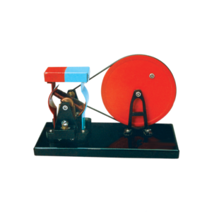
The dynamo model is mounted on a base with a driving wheel.
Output is through 4 mm sockets and a low voltage bulb is also provided as a simple output indicator.
Generates both AC and DC.
When the two brushes of the generator are put in the two ends of the commutator, the output is an AC.
When the brushes are put in the middle of the commutator, the output is a DC.
Includes Instructions.
Designed to demonstrate to implement and applications of electrical, electronic devices and simple circuits. These modules are fitted with 4 mm sockets.
Components are directly mounted on printed PCB with diagram.Various modules are available as following Resistor
LDR
LED
Push Switch
Motor
Reed Relay
Reed Switch
Relay Nand Gate
Buzzer
Thermistor
Lamp Holder
Single Pole Double Throw Switch
Electromagnet
Power Transistor
This heavy duty demountable transformer can be used for the study of transformertheory and many other alternating current phenomena.
This kit consists of:
1. A magnetic circuit made of highly permeable U shape metal sheet, which can be closed using two clamps with tightening screws.
2. Section: 40 x 40 mm with 150 mm length and 170 mm height.
3. One coil of 6000 turns with maximum current of 0.2 A. Intermediary coil of 2000 turns output.
4. One coil of 600 turns with maximum current of 2.5 A, which is mainly used to create the primary of transformer.
5. One coil of 1200 turns with maximum current of 1.25 A, fitted with intermediary 400 and 800 turns outputs.
6. One coil of 72 turns with maximum current of 12 A, fitted with intermediary 6, 30, 54 and 66 turns outputs.
7. Power supply cable.


Reviews
There are no reviews yet.