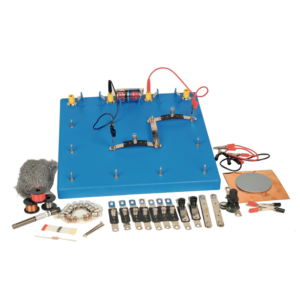
Enables students to investigate nature and properties of electricity by using simple circuits which are easily constructed on a base board.
The connector system uses P.C.B. strips with cut-out sections whose ends can easily be inserted in spring terminals, ensuring low contact resistance and ease of connection.
The kit consists of :
1. Baseboard, plastic, with spring terminals and three battery holders. (1)
2. Batteries. (3)
3. Lamps 1.25 V MES. (10)
4. Lamp holders mounted on PCB connectors. (6)
5. Plain connector PCBs. (10)
6. Wire wound potentiometer with crocodile clip connections. (1)
7. Silicon diode. (1)
8. Resistor 3.9 ohm 2.5 W (1)
9. Pair Leads, red, with crocodile clip at each end. (1)
10. Pair Leads, black, with crocodile clip at each end (1)
11. Pair Leads, yellow, with crocodile clips at each end. (1)
12. Switches mounted on PCB. connectors (2)
13. PVC rod 15 cm long (1)
14. Soft iron nails, 5 cm long (2)
15. Bare copper wire, swg 20 (2 m)
16. Bare eureka wire, swg 34 (2 m)
17. Plastic covered copper wire (2 m)
18. Electrode support (1)
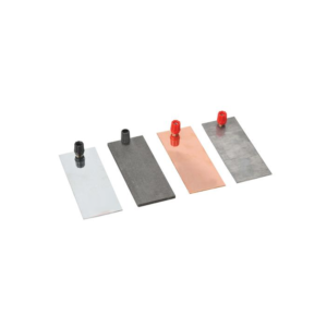
19. Pencil lead electrodes (10)
20. Sheet copper foil, 150 mm square (1)
21. Pack Steel wool (1)
22. Instruction manual in English. (1)
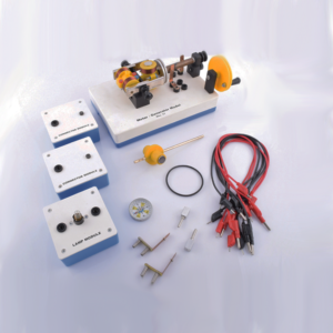
A simple form of D.C. motor with 2 pole armature wound with insulated copper wire and a permanent magnetic field provided by a removable bar magnet with a commutator and phosphor bronze brushes connected to 4 mm sockets, open construction, all parts visible.
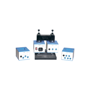
This heavy duty demountable transformer can be used for the study of transformertheory and many other alternating current phenomena.
This kit consists of:
1. A magnetic circuit made of highly permeable U shape metal sheet, which can be closed using two clamps with tightening screws.
2. Section: 40 x 40 mm with 150 mm length and 170 mm height.
3. One coil of 6000 turns with maximum current of 0.2 A. Intermediary coil of 2000 turns output.
4. One coil of 600 turns with maximum current of 2.5 A, which is mainly used to create the primary of transformer.
5. One coil of 1200 turns with maximum current of 1.25 A, fitted with intermediary 400 and 800 turns outputs.
6. One coil of 72 turns with maximum current of 12 A, fitted with intermediary 6, 30, 54 and 66 turns outputs.
7. Power supply cable.
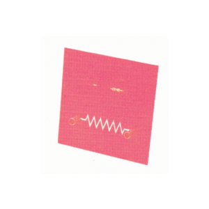
Designed to demonstrate to implement and applications of electrical, electronic devices and simple circuits. These modules are fitted with 4 mm sockets.
Components are directly mounted on printed PCB with diagram.Various modules are available as following Resistor
LDR
LED
Push Switch
Motor
Reed Relay
Reed Switch
Relay Nand Gate
Buzzer
Thermistor
Lamp Holder
Single Pole Double Throw Switch
Electromagnet
Power Transistor
Wound on rectangular bobbin, for use with 220 – 240 V AC mains with detachable mains connector with moulded plug, A 4 mm socket is provided for earthing.
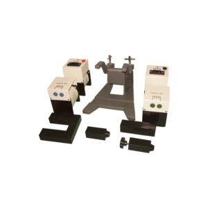
This motor-generator set gives students an insight into the physical and technical relationships on which electric motors, generators and transformers are based.
The modular system allows to set up different function models without tools: Various DC motors Series and shunt motor Synchronous motor DC generator and alternator Transformer.
This set allows the performance of 10 student experiments about the following topics:
Magnetic field of a coil
Conversion of electrical energy into kinetic energy
Commutator
Direct current motor
Synchronous motor
Series and shunt-wound motors
Electromagnetic induction
The electrical generator
Engine-generator
Transformer
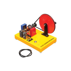
Generates both AC and DC.
When the two brushes of the generator are put in the two ends of the commutator, the output is an AC.
When the brushes are put in the middle of the commutator, the output is a DC.
Includes Instructions.

































Reviews
There are no reviews yet.