This panel is used to demonstrate the number systems such as binary, decimal and hexadecimal numbers. Toggle switches used to activate the displays showing the particular number entered. Input may be entered either as decimal or binary numbers with a toggle switch for mode selection. Decimal numbers are shown on a three digit seven segment LED display. 12 V / 2 A DC adaptor is required to operate it.
Objective:
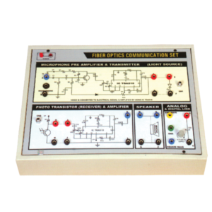
To construct an optical transmitter and transmission of signal through Fiber Optics Cable. To construct an Optical Receiver and study the Attenuation of Signal when transmitted from Transmitter to Receiver end. Analog and Digital link can also be studied as this unit is complete with Sine and Square Waves. Bending losses can also be studied.
Features:
Instrument comprises of Microphone Preamplifier stages consists of MIC (Microphone), Preamplifier and Amplifier (Voice is converted to electrical signal and then amplified) and fed to LED (Transmitter) and then through fibre cable, signal is sent to Photodetector (Transistor) and again amplifier and output is sent to Speaker Unit. Power Supply of +6 VDC is used in Amplifier ckt. 2 No. Fiber Optics cables are provided (one of them is 50 cm long and the other is 100 cm long). One more fiber cable of 50mm length having connector at one end is also provided. Connectors a both end of fiber cable are provided for insertion in sockets provided on the front panel. Bending losses can also be studied in long wire.
Standard: MIC with 2 meter long lead and a Speaker 4, 4 ohm are mounted in a vertical box.
Accuracy: with 1 meter long connecting leads. 2 No. Fiber optic cable having length of 50 cm and 100 cm are provided.
Optional : Digital multimeter (3 1/2 Digit, Big size Display) This model also include Digital Multimeter and wooden frame for measurement of Numerical aperture i.e. complete in all respect including facility for measurement of numerical aperture.
To demonstrate the function of operational amplifier using TL081 and L272 with discrete components different value of resistors, capacitor. Input can be applied from microphone, LDR. Offset null control is also provided. Output can be fed through the power amplifier into a loudspeaker.
Each module is housed in a plastic box 90 x 90 x 30 mm and is provided with a circuit diagram on the panel. It has necessary input and output sockets. The socket stacking system allows addition of as many modules as desired, designed to work on 6V D. C.
Logic Gates Trainer has been designed to study logic gates and applications. This trainer board is designed to verify the truth table of various logic functions, to prove De-Morgan’s theorem, Half adder and Full adder by using logic gates. The board is absolutely self-contained and requires no additional apparatus. 12 V / 1 A DC adaptor is required to operate it.


Reviews
There are no reviews yet.