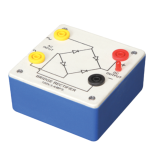
Bridge Rectifier is made of four diodes connected in a bridge circuit. It is housed in a plastic moulded box. This bridge rectifier converts alternating current (AC) into direct current (DC). It provides the same output polarity for either input polarity. All the electronic devices require direct current, so bridge rectifiers are used inside the power supplies of almost all electronic equipment. For the easy understanding of the internal circuitry, the circuit diagram is printed on the box.
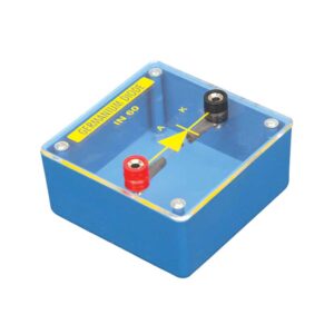
Diode mounted on transparent covered base for maximum visibility to students. Two four mm sockets one red and one black are provided for easy connections.
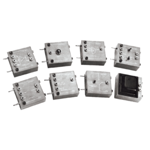
Each module is housed in a plastic box 90 x 90 x 30 mm and is provided with a circuit diagram on the panel. It has necessary input and output sockets. The socket stacking system allows addition of as many modules as desired, designed to work on 6V D. C.
This panel is used to demonstrate the number systems such as binary, decimal and hexadecimal numbers. Toggle switches used to activate the displays showing the particular number entered. Input may be entered either as decimal or binary numbers with a toggle switch for mode selection. Decimal numbers are shown on a three digit seven segment LED display. 12 V / 2 A DC adaptor is required to operate it.
A common anode seven segment module is fitted on a board with 8 bit dip switch to control the each segment of seven segment LED display. The inputs A-D of a display driver are connected to the binary coded decimal (BCD) outputs from a decade counter. A network of logic gates inside the display driver makes its outputs a-g become high or low as appropriate to light the required segments a-g of a seven segment display. A resistor is required in series with each segment to protect the LEDs
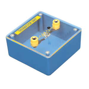
Mounted on transparent covered base for easy demonstration. Diagram and two sockets are provided for use with some circuit. Thermistor is mounted above the base to avoid the damage from heat.


































Reviews
There are no reviews yet.