


Description


Error: Contact form not found.
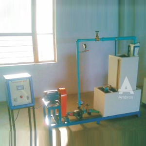
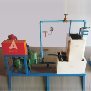
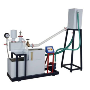
Centrifugal Pump Test Rig
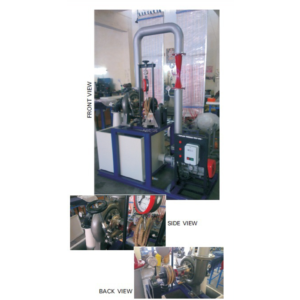
Closed Circuit Type With S.S. Tanks, ISI Mark Pumps & Motors, Powder coated The closed circuit test rig consists of a “kirloskar make” monoblock centrifugal pump. The pump is provided with a vacuum gauge on suction pipe and a pressure gauge on discharge pipe. The gate valve is used to adjust the head on the pump. The discharge is measured by measuring tank / water flow meter. The input power is measured by energy meter.
l. Centrifugal monoblock- 1 h.p.
2. Pressure gauge and vacuum gauge for measuring the head.
3. Measuring tank of 400×400 x400 mm OR Water flow energy meter for measuring the discharge.
4. Stop watch.
5. Sump tank of sufficient capacity.
6. Energymeter to measure input power.
7. A technical manual accompanies the equipment.
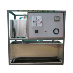
1. The equipment is coated with an attractive and anticorrosive powder coating.
2. The equipment consists of ISI standard
(i) Monoblock ————————- Kirloskar make
(ii) Energymeter ————————- Maxwell Jaipur make
(iii) Water flow meter ————————- Kranti/Anand make.
(i) 440 v, 15 A, stabilized three phase A.C. supply.
(ii) Floor area-2 mx2mxl.5m height
(iii) Tachometer for speed measurement (can be supplied at extra cost)
Description
| MODEL | HM 109 (1.33 HP) | HM 109 (5 HP) | |
| Output Power | 1.33 HP / 1 Kw | 5 HP / 3.75 Kw | |
| Discharge | 1500 LPM (Approx.) | 5000 LPM (Approx.) | |
| Supply Head | 5 m | 5 m | |
| Rope Brake Dynamometer | Dia 200 mm | Dia 300 mm | |
| Sump Tank | Capacity 300 Ltrs. | Capacity 600 Ltrs. | |
| Water Circulation Centrifugal Pump | Capacity 7 HP, Three Phase | Capacity 20 HP, Three Phase | |
| Speed | 1500 RPM (approx.) | ||
| Runner | With adjustable Curved Vanes | ||
| Discharge Measurement | Pitot Tube with Manometer | ||
| Control Panel | Star/Delta Starter, Mains Indicator, MCB for overload protection | ||
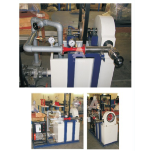
| The whole set-up is well designed and arranged in a good quality painted structure. | |||
| MODEL | HM 111 (1.33 HP) | HM 111 (2 HP) | HM 111 (5 HP) |
| Output Power | 1.33 HP / 1 Kw | 2 HP / 1.5 Kw | 5 HP / 3.75 Kw |
| Discharge | 300 LPM (Approx.) | 400 LPM (Approx.) | 630 LPM (Approx.) |
| Supply Head | 25 m | 40 m | 45 m |
| Rope Brake Dynamometer | Dia 200 mm | Dia 200 mm | Dia 300 mm |
| Sump Tank | Capacity 150 Liters. | Capacity 200 Liters. | Capacity 300 Liters. |
| Water Circulation Centrifugal Pump | Capacity 5 HP, Three Phase | Capacity 7.5 HP, Three Phase | Capacity 15 HP, Three Phase |
| Speed | 1000 RPM (approx.) | ||
| Impeller | Material Brass, Bucket type | ||
| Nozzle | Material Stainless Steel/Mild Steel | ||
| Spear | Material Stainless Steel/Mild Steel | ||
| Discharge Measurement | Pitot Tube with Manometer | ||
| Control Panel | Star/Delta Starter, Mains Indicator, MCB for overload protection | ||
| The whole set-up is well designed and arranged in a good quality painted structure. | |||
Error: Contact form not found.
WhatsApp us
No account yet?
Create an Account
Reviews
There are no reviews yet.