[contact-form-7 404 "Not Found"]
Centrifugal Pump Test Rig
Centrifugal Pump Test Rig
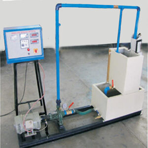
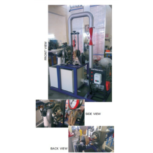
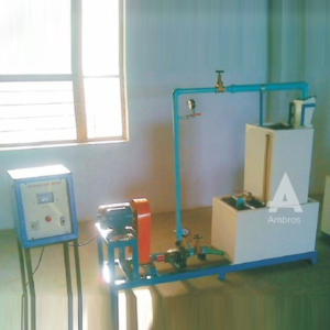
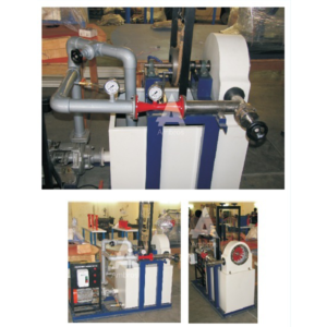
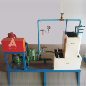
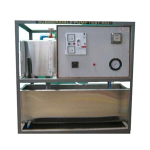
Closed Circuit Type With S.S. Tanks, ISI Mark Pumps & Motors, Powder coated The closed circuit test rig consists of a “kirloskar make” monoblock centrifugal pump. The pump is provided with a vacuum gauge on suction pipe and a pressure gauge on discharge pipe. The gate valve is used to adjust the head on the pump. The discharge is measured by measuring tank / water flow meter. The input power is measured by energy meter.
Specifications:
l. Centrifugal monoblock- 1 h.p. 2. Pressure gauge and vacuum gauge for measuring the head. 3. Measuring tank of 400×400 x400 mm OR Water flow energy meter for measuring the discharge. 4. Stop watch. 5. Sump tank of sufficient capacity. 6. Energymeter to measure input power. 7. A technical manual accompanies the equipment.Features:
1. The equipment is coated with an attractive and anticorrosive powder coating. 2. The equipment consists of ISI standard (i) Monoblock ————————- Kirloskar make (ii) Energymeter ————————- Maxwell Jaipur make (iii) Water flow meter ————————- Kranti/Anand make.Services required :
(i) 440 v, 15 A, stabilized three phase A.C. supply. (ii) Floor area-2 mx2mxl.5m height (iii) Tachometer for speed measurement (can be supplied at extra cost)francis turbine test setup
DESCRIPTION:
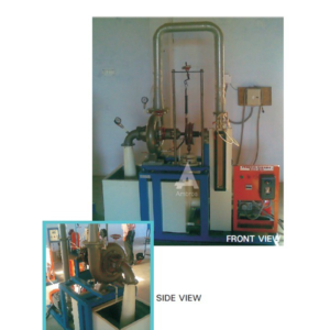
Francis Turbine is a reaction Turbine, which was developed by English born American Engineer Sir J.B. Francis. The water enters the turbine through the outer periphery of the runner in the radial direction and leaves the runner in axial direction and hence it is called a mixed flow turbine. As the water flows to the runner, a part of pressure energy goes on changing into kinetic energy. Thus the water through the runner is under pressure. The runner is completely enclosed in an air tight casing and the casing & runner is always full of water. The present Set-up consists of a runner. The water is fed to the turbine by Means of centrifugal Pump, radially to the runner. The runner is directly mounted on one end of a central SS shaft and other end is connected to a brake arrangement. The circular window of the turbine casing is provided with a transparent. The circular window of the turbine casing is provided with a transparent acrylic sheet for observation of flow on to the runner. The runner assembly is supported by thick cast iron pedestal. Load is applied to the turbine with the help of brake arrangement so that the efficiency of the turbine can be calculated. A draught tube is fitted on the outlet of the turbine. The Set-up is complete with guide mechanism. Pressure and vacuum Gauge are fitted at the Inlet and Outlet of the turbine to measure the total supply head on the turbine.UTILITIES REQUIRED:
● Water Supply and Drain.● Electricity 15 kW, 440V Ac, Three Phase
TECHNICAL SPECIFICATIONS:
| MODEL | HM 101 (1.33 HP) | HM 101 (2 HP) | HM 101 (5 HP) |
| Output Power | 1.33 HP / 1 Kw | 2 HP / 1 Kw | 5 HP / 3.75 Kw |
| Discharge | 1000 LPM (Approx.) | 1000 LPM (Approx.) | 2000 LPM (Approx.) |
| Supply Head | 10 m | 10 m | 15 m |
| Rope Brake Dynamometer | Dia 200 mm | Dia 200 mm | Dia 300 mm |
| Sump Tank | Capacity 300 Ltrs. | Capacity 300 Ltrs. | Capacity 600 Ltrs. |
| Water Circulation Centrifugal Pump | Capacity 5 HP, Three Phase | Capacity 5 HP, Three Phase | Capacity 15 HP, Three Phase |
| Speed | 1500 RPM (approx.) | ||
| Runner | Having Curved Vanes | ||
| Discharge Measurement | Pitot Tube with Manometer | ||
| Control Panel | Star/Delta Starter, Mains Indicator, MCB for overload protection | ||
| The whole set-up is well designed and arranged in a good quality painted structure. | |||
Gear Pump Test Setup
DESCRIPTION:
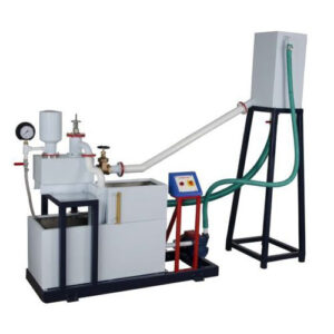
The Set-up is designed to study the performance of Gear Pump. The Set-up consists of a Gear Pump having a pair of meshed gears coupled with electrical motor, supply tank, measuring tank & pipe fittings for closed loop oil circulation. Pressure and Vacuum Gauges are connected on delivery and suction side of pump for the purpose of measurement. The flow rate of water is measured using measuring tank and stop watch provided.EXPERIMENT:
Ø To determine overall efficiency and pump efficiency of the Gear Pump Ø To plot Head vs. Discharge, Pump efficiency vs. DischargeFEATURES:
Ø Closed loop water circulation Ø Compact & stand alone set-up Ø MS Excel sample calculation program on demand Ø Stainless Steel tanks and wetted parts Ø Superb painted structure Ø Simple to Operate & MaintainUTILITIES REQUIRED:
Electric Supply: – Provide 230 +/- 10 VAC, 50 Hz, Single Phase Electric Supply with proper earthing. (Neutral – Earth voltage less than 5 VAC) 5 A, three pin socket with switch for pump. Oil Supply: Oil @ 30 Ltrs. (Optional extra cost)TECHNICALS SPECIFICATIONS:
Ø Pump : Gear Pump with pair of meshed gears Capacity 1 HP,Speed 1500 RPM (max.), Head 5 Kg/cm2 (max.) Ø Drive : AC Motor with step cone pulley arrangement for 3 prefixed speed DC Motor with DC Drive along with (non-contact type Digital RPM Indicator Ø Supply Tank : Capacity 30 Ltrs. Ø Measuring Tank : Capacity 20 Ltrs. fitted with Piezometer Tube & Scale Ø Piping : GI / PVC Ø Stop Watch : Electronic Ø Control Panel : With required electrical instrumentation (The whole Set-up is well designed and arranged in a good quality painted structure.Hydraulic Ram Test Setup
DESCRIPTION:
The Set-up is designed to study the Hydraulic Ram. Hydraulic RAM is used for pump little quantity of water to high head from a large quantity of water available at low head. It works on a principle of water hammer stating that “When flowing water is suddenly stopped in a long pipe a pressure wave travels along the pipe creating an effect of water hammer”. The Set-up consists of a pipe section fitted with a pulse valve and non-return valve, a supply reservoir on a stand which is connected to an overhead tank, an air vessel above the valve chamber smoothes cyclic fluctuations from the Ram delivery. Different pressure may be applied to the pulse valve to change the closing pressure and hence the operating characteristic. The flow rate of useful and waste water is measured using measuring tank and stop watch provided. Pressure and Vacuum Gauge are connected on delivery and suction side for the purpose of measurement.EXPERIMENT:
Ø To find out discharge of useful water and waste water. Ø To find out the efficiency of the Hydraulic RAMFEATURES:
Ø Closed loop water circulation Ø Compact & stand alone set-up Ø MS Excel sample calculation program on demand Ø Stainless Steel tanks and wetted parts Ø Superb painted structure Ø Simple to Operate & MaintainUTILITIES REQUIRED:
Electric Supply: – Provide 230 +/- 10 VAC, 50 Hz, Single Phase Electric Supply with proper earthing. (Neutral – Earth voltage less than 5 VAC) 5 A, three pin socket with switch for pump. Water Supply: Tap water connection ½ “ BSP Distilled water @ 90 Ltrs. (Optional)TECHNICAL SPECIFICATIONS:
Ø Product : Hydraulic RAM Ø RAM : Size 50 x 15 mm, Supply Head 2.5m, Delivery Head 10 m (max.) Ø Air Vessel : Suitable Capacity MOC SS Ø Delivery Line : For RAM, Dia 50 mm Length 6 m. Ø Pump : Capacity 1 HP, Crompton / Sharp / Hero make Ø Supply Tank : Capacity 150 Ltrs. Ø Overhead Tank : Capacity 100 Ltrs. Ø Measuring Tank : Suitable Capacity one each for useful and waste MOC SS fitted (2 Nos.) with Piezometer Tube & Scale Ø Piping : GI / PVC Ø Stop Watch : Electronic Ø Pressure Gauge : Bourdon Type Ø Control Panel : Comprises of Standard make On/Off Switch, Mains Indicator etc. Ø Tanks will be made of Stainless Steel. Ø The whole Set-up is well designed and arranged in a good quality painted structure.Jet Pump Test Setup
DESCRIPTION:
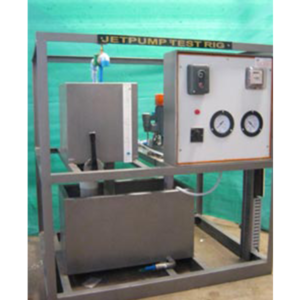
The Set-up is designed to study the performance of Jet Pump. The Set-up consists of a Mono-Block Jet Pump coupled with electrical motor, supply tank, measuring tank & pipe fittings for closed loop oil circulation. Pressure and Vacuum Gauges are connected on delivery and suction side of pump for the purpose of measurement. The flow rate of water is measured using measuring tank and stop watch provided.EXPERIMENT:
Ø To determine overall efficiency and pump efficiency of the Jet Pump Ø To plot Head vs. Discharge, Pump efficiency vs. DischargeFEATURES:
Ø Closed loop water circulation Ø Compact & stand alone set-up Ø MS Excel sample calculation program on demand Ø Stainless Steel tanks and wetted parts Ø Superb painted structure Ø Simple to Operate & MaintainUTILITIES REQUIRED:
1.Electric Supply: – Provide 230 +/- 10 VAC, 50 Hz, Single Phase Electric Supply with proper earthing. (Neutral – Earth voltage less than 5 VAC) 5 A, three pin socket with switch for pump. 2.Water Supply: Tap water connection ½ “BSP, Distilled water @ 90 Ltrs. (Optional)TECHNICAL SPECIFICATIONS:
Ø Product : Mono – Block Jet Pump Test Rig Ø Pump & Drive : Mono – Block Jet Pump, Size 32 mm x 25 mm x 25 mm (Suction x Pressure x Delivery), Capacity 1 HP Ø Supply Tank : Capacity 70 Ltrs. Ø Measuring Tank : Capacity 50 Ltrs fitted with Piezometer Tube & Scale Ø Medium Flow : Clear Water Ø Piping : GI / PVC Ø Stop Watch : Electronic Ø Pressure Gauge : Bourdon Type Ø Control Panel : Comprises of Energy Measurement : Energy meter Electronics, L & T make Ø MCB : For Overload Protection Standard make On/Off Switch, Main Indicator etc. Ø The whole Set-up is well designed and arranged in a good quality painted structure.Kaplan Turbine Test Setup
DESCRIPTION:
Kaplan Turbine is an axial flow reaction Turbine named in honor of Dr. B. Kaplan, a Gennan Engineer. This turbine is suitable for low head. The power produced by a turbine is proportional to QH. As the head (H) decreases the J discharge (Q) must increase to produce the same power. The present Set-up consists of a scroll casing housing a runner. Water enters the turbine through the stationary guide vanes and passes through the runner axially. The runner has a hub and airfoil vanes, which are mounted on it. The water is fed to the turbine by means of Centrifugal Pump. The runner is directly mounted on one end of a central SS shaft and other end is connected to a brake arrangement. A transparent hollow cylinder made of acrylic is fitted in between the draught tube and the casing for observation of flow on to the airfoil vanes. This runner assembly is supported by thick cast iron pedestal. Load is applied to the turbine with the help of this brake arrangement so that the efficiency of the turbine can be calculated. The Set-up is supplied with control panel. A draught tube is fitted on the Outlet of the turbine. The Set-up is complete with guide mechanism. Pressure and Vacuum Gauge are fitted at the Inlet & Outlet of the turbine to measure the total supply head on the turbine.EXPERIMENT:
1.To study the operation of a Kaplan Turbine 2.To determine the Output Power of Kaplan Turbine 3.To determine the Turbine EfficiencyUTILITIES REQUIRED:
● Water Supply and Drain.● Electricity 15 kW, 440V AC, Three Phase
TECHNICAL SPECIFICATIONS:
| MODEL | HM 109 (1.33 HP) | HM 109 (5 HP) | |
| Output Power | 1.33 HP / 1 Kw | 5 HP / 3.75 Kw | |
| Discharge | 1500 LPM (Approx.) | 5000 LPM (Approx.) | |
| Supply Head | 5 m | 5 m | |
| Rope Brake Dynamometer | Dia 200 mm | Dia 300 mm | |
| Sump Tank | Capacity 300 Ltrs. | Capacity 600 Ltrs. | |
| Water Circulation Centrifugal Pump | Capacity 7 HP, Three Phase | Capacity 20 HP, Three Phase | |
| Speed | 1500 RPM (approx.) | ||
| Runner | With adjustable Curved Vanes | ||
| Discharge Measurement | Pitot Tube with Manometer | ||
| Control Panel | Star/Delta Starter, Mains Indicator, MCB for overload protection | ||
| The whole set-up is well designed and arranged in a good quality painted structure. | |||
Multi Stage Centrifugal Pump Test Setup
DESCRIPTION:
The Set-up is designed to study the performance of Multi Stage Centrifugal Pump. The Set-up consists of a Multi Stage Centrifugal Pump coupled with DC motor & drive, supply tank, measuring tank & pipe fittings for closed loop water circulation. There are 2 separate pumps connected to DC Motor and drive and can be connected in series and parallel to stimulate different combinations. Pressure and Vacuum Gauge are connected on delivery and suction side of each pump for the purpose of measurement. Swinging Field Dynamometer arrangement for direct torque measurement using dial type spring balance is made for individual pump. The flow rate of water is measured using measuring tank and stop watch provided.EXPERIMENTS:
1.Speed Vs Discharge 2.Head Vs Discharge at various speeds 3.Efficiency curves at various speed and headsFEATURES:
1.Closed loop water circulation 2.Compact & stand alone set-up 3.MS Excel sample calculation program on demand 4.Stainless Steel tanks and wetted parts 5.Superb painted structure 6.Simple to Operate & MaintainUTILITIES REQUIRED:
1.Electric Supply: – Provide 230 +/- 10 VAC, 50 Hz, Single Phase Electric Supply with proper earthing. (Neutral – Earth voltage less than 5 VAC), 5 A, three pin socket with switch for pump. 2.Water Supply: Tap water connection ½” BSP. Distilled water @ 80 Ltrs. (Optional extra cost)TECHNICAL SPECIFICATIONS:
1.Pump (2 Nos.) : Kirloskar, Capacity 1 HP Speed 2800 RPM (max.) Head 12 m (max.) 2.Drive : DC Drive along with non-contact type Digital RPM Indicator 3.Supply Tank : Capacity 150 Ltrs. 4.Measuring Tank : Capacity 100 Ltrs. fitted with Piezometer Tube & Scale 5.Piping : GI / PVC 6.Stop Watch : Electronic 7.Control Panel : With required electrical instrumentation The whole Set-up is well designed and arranged in a good quality painted structure.Pelton Wheel Turbine Test Setup
DESCRIPTION:
Pelton Wheel Turbine is only impulse water turbine now in common use named in honor of Sir L.A. Pelton (1829-1908) of California, USA. It is a tangential flow impulse turbine. The water strikes the buckets along the tangent of the runner. The energy available at the Inlet of the Turbine is only kinetic energy. The Pressure at the Inlet and Outlet of the atmospheric. This turbine is used for high heads. The Present Set-up consists of a runner. The buckets are mounted on the runner. The water is fed to the turbine, through SS nozzle with a SS spear, by means of Centrifugal Pump, tangentially to the runner. Row of water into turbine is regulated by adjusting the spear position by the help of a given hand wheel the runner is directly mounted on one end of a central SS shaft and other end is connected to a brake arrangement. The circular window of the turbine casing is providing with a transparent acrylic sheet for observation of flow on to the buckets. This runner assembly is supported by rigid MS structure. Load is applied to the turbine with the help of this brake dynamometer so that the efficiency of the turbine can be calculated. Pressure Gauge is fitted at the Inlet of the turbine to measure the total supply head to the turbine.EXPERIMENT:
1.To study the operation of a Pelton Wheel Turbine 2.To determine the Output Power of Pelton Wheel Turbine 3.To determine the Turbine EfficiencyUTILITIES REQUIRED:
● Water Supply and Drain.● Electricity 15 kW, 440V AC, Three Phase
TECHNICAL SPECIFICATIONS:
| MODEL | HM 111 (1.33 HP) | HM 111 (2 HP) | HM 111 (5 HP) |
| Output Power | 1.33 HP / 1 Kw | 2 HP / 1.5 Kw | 5 HP / 3.75 Kw |
| Discharge | 300 LPM (Approx.) | 400 LPM (Approx.) | 630 LPM (Approx.) |
| Supply Head | 25 m | 40 m | 45 m |
| Rope Brake Dynamometer | Dia 200 mm | Dia 200 mm | Dia 300 mm |
| Sump Tank | Capacity 150 Liters. | Capacity 200 Liters. | Capacity 300 Liters. |
| Water Circulation Centrifugal Pump | Capacity 5 HP, Three Phase | Capacity 7.5 HP, Three Phase | Capacity 15 HP, Three Phase |
| Speed | 1000 RPM (approx.) | ||
| Impeller | Material Brass, Bucket type | ||
| Nozzle | Material Stainless Steel/Mild Steel | ||
| Spear | Material Stainless Steel/Mild Steel | ||
| Discharge Measurement | Pitot Tube with Manometer | ||
| Control Panel | Star/Delta Starter, Mains Indicator, MCB for overload protection | ||
| The whole set-up is well designed and arranged in a good quality painted structure. | |||
