Apparatus is designed primarily for demonstration of the basic principles of transformers.
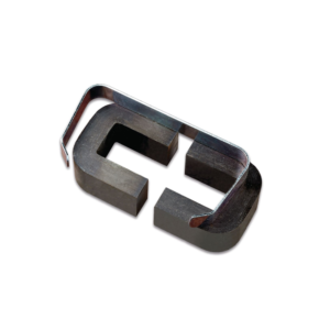
It consists of a laminated U-core with laminated I-core, both with 32 x 25 mm cross section to form a closed core of size 102 x 127 mm.
Heavy aluminium alloy stand with removable clamping rods, 2 pole pieces, each 65 x 30 x 25 mm with one end cone shaped, to accept support rod and shading ring.
Poles also have a hole drilled through lengthwise to take a light beam. 300 turns 600 turns 1200 turns 3600 turns 12000 turns
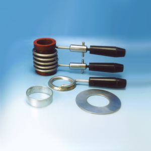
Comprising 1 welding coil of 5 turns on former with insulated handle and short-circuiting pins,1 annular melting trough with insulated handle to show heating by induction,1 jumping ring which is thrown clear when primary current is started and a floating ring which remains freely suspended when primary current is flowing.
A simple form of D.C. motor with 2 pole armature wound with insulated copper wire and a permanent magnetic field provided by a removable bar magnet with a commutator and phosphor bronze brushes connected to 4 mm sockets, open construction, all parts visible.
For Westminster Electromagnetic Kit giving 1 V full wave rectified DC and 1 V / 2 V AC outputs at 8 A max.
The circuit diagram is printed on the top panel which also carries mains switch, light indicator and output sockets for DC and AC With 1.5 meter mains detachable cable.
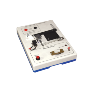
Investigate the working principle of circuit breaker type fuse with this demonstration model.
The apparatus is built on a robust plastic base and includes resistive loads to simulate external wiring circuits.
Applications of the thermal response of bimetal strips and also electromagnetism (movement from a solenoid) are clearly demonstrated in this model.
When a 12 V DC supply is connected (not supplied) the LED lights to show that current is flowing in the external circuit and the bi-metal strip can be seen to bend as its heater coil raises the temperature.
After a few minutes the bending is sufficient to trip the mechanism and the current path is broken.
At any current selection a short circuit situation can be initiated by pressing the red button and this produces an immediate response from the solenoid to disconnect the supply.
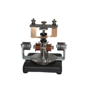
The motor consists of a two pole armature mounted between the ends of two bar magnets.
The armature has a two section commutator and a pair of slip-rings on its shaft and is so constructed that the wire cannot slip off the iron core.
The upper bearing and brushes for the commutator are mounted on a strong upright.
Separate brushes are provided for the commutator and for slip rings and each are connected to a terminal.
The magnets are held in position by thumb screws.


































Reviews
There are no reviews yet.