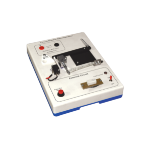
Description
A very effective and motivating learning aid in elementary electromagnetism.
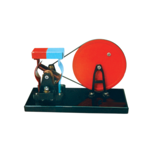
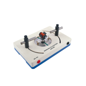
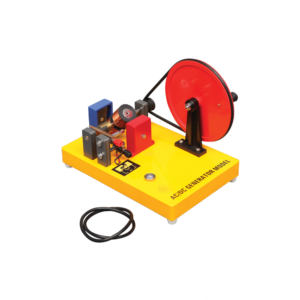
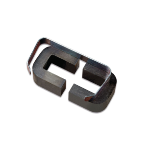
Consists of 8 anisotropic alloy magnets, 8 ceramic ferrite magnets, 4 steel magnet yokes, 6 plotting compasses, 4 hardboard formers to take compasses, 1 bottle iron filings 250 gm, 4 dispensers for iron filings , 4 double C-cores, 4 clips for C cores, 4 Aluminium rings, 4 Aluminium split rings, 4 armatures with axle tubes, 4 Aluminium axle rods, 8 split pins, 16 rivets, 4 formers for coils, 4 reels cello tape, 4 reels copper wire, 4 sheets white pasteboard, 4 plain postcards, 4 reels white cotton thread, 1 length latex rubber tubing, 4 each resistors 100 ohms and 10 ohms, 4 support bases, 10 MES bulbs, 8 MES bulb holders,1 wood clamp and 1 wooden block.
With instructions.


Reviews
There are no reviews yet.