Students can explore how a simple electric motor works by doing a series of investigations.
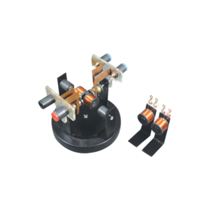
This St. Louis motor can be adjusted so students can study the effect of voltage and position of the brushes on the commutator.
The motor consists of a two pole DC armature. The brush holder, with two heavy binding post terminals, can be rotated for experiments.
The permanent bar magnets, supported by clamps, can be adjusted to the desired location.
This apparatus requires 4 D cell batteries with holder (not included) or a power supply and two connecting leads (not included).
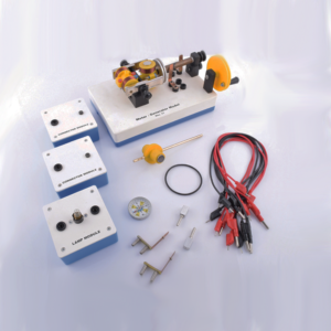
This motor-generator set gives students an insight into the physical and technical relationships on which electric motors, generators and transformers are based.
The modular system allows to set up different function models without tools: Various DC motors Series and shunt motor Synchronous motor DC generator and alternator Transformer.
This set allows the performance of 10 student experiments about the following topics:
Magnetic field of a coil
Conversion of electrical energy into kinetic energy
Commutator
Direct current motor
Synchronous motor
Series and shunt-wound motors
Electromagnetic induction
The electrical generator
Engine-generator
Transformer
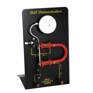
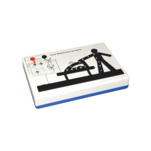
This apparatus is an effective demonstration of how the earth wire and fuse act together to protect both the user and the appliance.
When the appliance is connected correctly and the LEDs in the appliance will illuminate to show the appliance is working.
A fault is then demonstrated by swapping the live wire from inside the appliance to the case to show either the fuse melts (protecting the user and appliance) or in the case of no earth wire, the LEDs illuminate to indicate the passage of current through the person to ground.
The fuse is easily visible and can be seen to ‘blow’ when a fault occurs.The unit is supplied with 10 m of fuse wire and full instructions.
A 12 V DC power supply is required.
Connections are made via 4 mm shrouded sockets.
Comprising 1 welding coil of 5 turns on former with insulated handle and short-circuiting pins,1 annular melting trough with insulated handle to show heating by induction,1 jumping ring which is thrown clear when primary current is started and a floating ring which remains freely suspended when primary current is flowing.
This heavy duty demountable transformer can be used for the study of transformertheory and many other alternating current phenomena.
This kit consists of:
1. A magnetic circuit made of highly permeable U shape metal sheet, which can be closed using two clamps with tightening screws.
2. Section: 40 x 40 mm with 150 mm length and 170 mm height.
3. One coil of 6000 turns with maximum current of 0.2 A. Intermediary coil of 2000 turns output.
4. One coil of 600 turns with maximum current of 2.5 A, which is mainly used to create the primary of transformer.
5. One coil of 1200 turns with maximum current of 1.25 A, fitted with intermediary 400 and 800 turns outputs.
6. One coil of 72 turns with maximum current of 12 A, fitted with intermediary 6, 30, 54 and 66 turns outputs.
7. Power supply cable.
For Westminster Electromagnetic Kit giving 1 V full wave rectified DC and 1 V / 2 V AC outputs at 8 A max.
The circuit diagram is printed on the top panel which also carries mains switch, light indicator and output sockets for DC and AC With 1.5 meter mains detachable cable.
Apparatus is designed primarily for demonstration of the basic principles of transformers.
It consists of a laminated U-core with laminated I-core, both with 32 x 25 mm cross section to form a closed core of size 102 x 127 mm.
Heavy aluminium alloy stand with removable clamping rods, 2 pole pieces, each 65 x 30 x 25 mm with one end cone shaped, to accept support rod and shading ring.
Poles also have a hole drilled through lengthwise to take a light beam. 300 turns 600 turns 1200 turns 3600 turns 12000 turns


Reviews
There are no reviews yet.