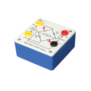
Bridge rectifier is designed with four LEDs internally arranged in bridge pattern fitted inside a plastic moulded case. Two LED’s are red and two LED’s are green. This device is used to demonstrate the functioning of a bridge rectifier, i.e., to convert alternating current (AC) into direct current (DC). Two yellow sockets are used for AC input. Two sockets, one red and one black, are used for DC output. For the easy understanding of the internal circuitry, the circuit diagram is printed on the box.
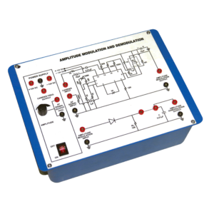
Instrument is design to demonstrate the method to transmit signals via. Electromagnetic transmission. It is still used in radio system to transmit audio signal although it has lesser in popularity compared to FM (Frequency Modulation) due to its lower signal to noise ratio.
Technical Specification :-
1. I C based DC regulated Power Supply ±12 V / 500 mA.
2. Audio frequency 1 KHz / 0-2 Vpp for modulating signal 455 KHz / 2.5 Vpp approx. for Carrier Frequency.
This panel is used to demonstrate the number systems such as binary, decimal and hexadecimal numbers. Toggle switches used to activate the displays showing the particular number entered. Input may be entered either as decimal or binary numbers with a toggle switch for mode selection. Decimal numbers are shown on a three digit seven segment LED display. 12 V / 2 A DC adaptor is required to operate it.



































admin –
Good