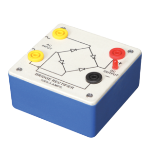
Bridge Rectifier is made of four diodes connected in a bridge circuit. It is housed in a plastic moulded box. This bridge rectifier converts alternating current (AC) into direct current (DC). It provides the same output polarity for either input polarity. All the electronic devices require direct current, so bridge rectifiers are used inside the power supplies of almost all electronic equipment. For the easy understanding of the internal circuitry, the circuit diagram is printed on the box.
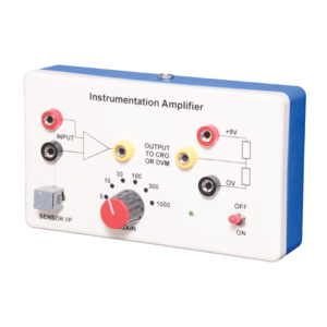
Instrumentation amplifier is a switched gain precision operation amplifier. This is used for precise and accurate, low noise differential signal acquisition. 4mm sockets are used for the input signal. It can be interfaced with a wide range of sensors. It can take small voltage changes from a sensor and make those changes large enough to be measured using CRO. It is not able to drive a low impedance load such as a loudspeaker or relay. The output can be read on CRO. Digital multimeter may also be used to read the output. With switched gain of 5 to 1000, it can handle signal inputs over a very wide range making it suitable for almost all applications.
Objective:
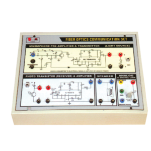
To construct an optical transmitter and transmission of signal through Fiber Optics Cable. To construct an Optical Receiver and study the Attenuation of Signal when transmitted from Transmitter to Receiver end. Analog and Digital link can also be studied as this unit is complete with Sine and Square Waves. Bending losses can also be studied.
Features:
Instrument comprises of Microphone Preamplifier stages consists of MIC (Microphone), Preamplifier and Amplifier (Voice is converted to electrical signal and then amplified) and fed to LED (Transmitter) and then through fibre cable, signal is sent to Photodetector (Transistor) and again amplifier and output is sent to Speaker Unit. Power Supply of +6 VDC is used in Amplifier ckt. 2 No. Fiber Optics cables are provided (one of them is 50 cm long and the other is 100 cm long). One more fiber cable of 50mm length having connector at one end is also provided. Connectors a both end of fiber cable are provided for insertion in sockets provided on the front panel. Bending losses can also be studied in long wire.
Standard: MIC with 2 meter long lead and a Speaker 4, 4 ohm are mounted in a vertical box.
Accuracy: with 1 meter long connecting leads. 2 No. Fiber optic cable having length of 50 cm and 100 cm are provided.
Optional : Digital multimeter (3 1/2 Digit, Big size Display) This model also include Digital Multimeter and wooden frame for measurement of Numerical aperture i.e. complete in all respect including facility for measurement of numerical aperture.
Lorem Ipsum is simply dummy text of the printing and typesetting industry. Lorem Ipsum has been the industry's standard dummy text ever since the 1500s, when an unknown printer took a galley of type and scrambled it to make a type specimen book. It has survived not only five centuries, but also the leap into electronic typesetting, remaining essentially unchanged. It was popularised in the 1960s with the release of Letraset sheets containing Lorem Ipsum passages, and more recently with desktop publishing software like Aldus PageMaker including versions of Lorem Ipsum.
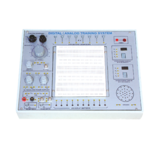
Solderless Breadboard has 1680 tie points. Provided with 2 Terminal strips and 4 Distribution strips. Built in DC Regulated Power Supply. DC Supply ± 5V/ 1 Amp. 0 to ± 15V DC (Variable), 1 Amp. Built-in Function Generator. . Waveform : Sine, Square and Triangle (with selector switch),
Frequency : 1 – 100 Hz Variable
Amplitude : Variable up to 10 V, TTL 5V p-p
Data Switches (Bounceless) – 8 No.
LED Display (buffered) – 10 No.
Clock Pulsar – 2 No.
Seven Segment Display with Decoder IC 7447 – 2 No.
Speaker 2.5 Dia. with sockets – 1 No.
BNC Plug with 2 mm Sockets – 2 No.
4 mm socket connected with 2 mm sockets – 2 No.
Interconnection leads having 2 mm plugs at one end – 10 No.
Interconnection leads having 4 mm plugs at both end – 10 No.
22 SWG Hook Up Wire of 20 cm length – 100 No.
Comprehensive User’s Manual – 1 No.
Input 220 V, 50 Hz. AC with On/Off indicator.

































Reviews
There are no reviews yet.