A common anode seven segment module is fitted on a board with 8 bit dip switch to control the each segment of seven segment LED display. The inputs A-D of a display driver are connected to the binary coded decimal (BCD) outputs from a decade counter. A network of logic gates inside the display driver makes its outputs a-g become high or low as appropriate to light the required segments a-g of a seven segment display. A resistor is required in series with each segment to protect the LEDs
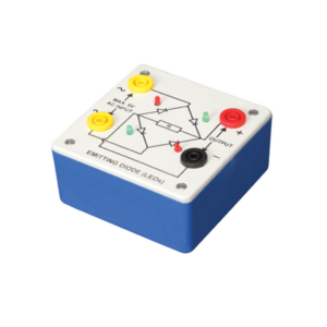
Bridge rectifier is designed with four LEDs internally arranged in bridge pattern fitted inside a plastic moulded case. Two LED’s are red and two LED’s are green. This device is used to demonstrate the functioning of a bridge rectifier, i.e., to convert alternating current (AC) into direct current (DC). Two yellow sockets are used for AC input. Two sockets, one red and one black, are used for DC output. For the easy understanding of the internal circuitry, the circuit diagram is printed on the box.
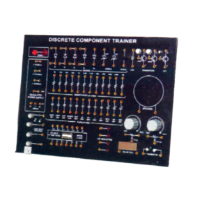
Trainer consisting of Power Supply of +5 V / ±12 V (each of 250 mA), Silicon, Germanium diodes, Zeners, PNP and NPN Transistors, FET, One speaker, 12 different values of carbon film resistances of ¼ W, ½ W and 1 W. 12 assorted values of capacitors from 100 pF to 1000 ?F, Integrated Circuit (IC) Base and IC 74LS00 1 No. each. LED, LDR, Photo diode, Solar Cell Logic Switches (4 No.) and LED Indicators (4 No.) etc., 2 mm Interconnection Leads -10 No. and Comprehensive User’s Manual
Objective : To plot Frequency Vs. Current Characteristics of LCR circuit when connected in series or in parallel.
Features : Instrument comprises of 3 Resistances, 3 Capacitors and 1 Inductance connected inside and connections brought out at Sockets. 2 AC moving coil meters to measure voltage and current.
Optional Acc. : Audio Frequency Function Generator
This panel is used to demonstrate the number systems such as binary, decimal and hexadecimal numbers. Toggle switches used to activate the displays showing the particular number entered. Input may be entered either as decimal or binary numbers with a toggle switch for mode selection. Decimal numbers are shown on a three digit seven segment LED display. 12 V / 2 A DC adaptor is required to operate it.
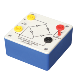
Bridge Rectifier is made of four diodes connected in a bridge circuit. It is housed in a plastic moulded box. This bridge rectifier converts alternating current (AC) into direct current (DC). It provides the same output polarity for either input polarity. All the electronic devices require direct current, so bridge rectifiers are used inside the power supplies of almost all electronic equipment. For the easy understanding of the internal circuitry, the circuit diagram is printed on the box.



































admin –
Good