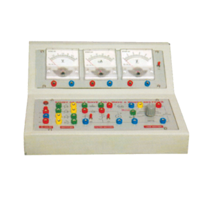
Objective : To study Efficiency and Ripple factor in case of Half wave, Full wave and Bridge rectifier on application of load and filters.
Features : Instrument comprises of AC Power Supply, 3 meters to measure Output Voltage, Output Current and ripple factor on electronic AC Voltmeter, 4 PN Junction Diodes, Filter Circuit kit, load Resistances selectable using bandswitch and all important connections points at 4mm Sockets.
Optional Acc : Digital AC millivoltmeter.
This Trainer Consist of :
1. Regulated power supply of ± 12 V / 250 mA.
2. Variable 0 to ±5 V / 250 mA.
3. Sine wave oscillation of 1 KHz.
4. Digital Voltmeter of 0-20 V DC, LCD display, 3 ½ Digit.
5. Functional diagram of IC 741 is printed with 2 mm sockets.
6. One extra 8 pin IC Base with 2 mm sockets.
7. Potentiometer of 10K Ohms.
8. Required Resistance and Capacitances mounted on board.
9. Interconnection Leads and Manual to perform 15 experiments on IC741 e.g. inverting, non-inverting, summing, difference, multiplier, differentiator, integrator etc.
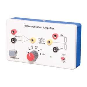
Instrumentation amplifier is a switched gain precision operation amplifier. This is used for precise and accurate, low noise differential signal acquisition. 4mm sockets are used for the input signal. It can be interfaced with a wide range of sensors. It can take small voltage changes from a sensor and make those changes large enough to be measured using CRO. It is not able to drive a low impedance load such as a loudspeaker or relay. The output can be read on CRO. Digital multimeter may also be used to read the output. With switched gain of 5 to 1000, it can handle signal inputs over a very wide range making it suitable for almost all applications.
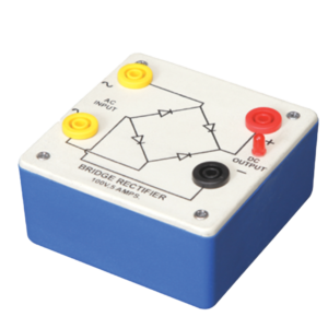
Bridge Rectifier is made of four diodes connected in a bridge circuit. It is housed in a plastic moulded box. This bridge rectifier converts alternating current (AC) into direct current (DC). It provides the same output polarity for either input polarity. All the electronic devices require direct current, so bridge rectifiers are used inside the power supplies of almost all electronic equipment. For the easy understanding of the internal circuitry, the circuit diagram is printed on the box.
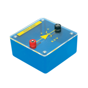
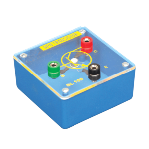
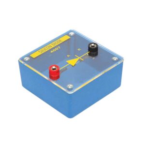
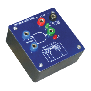
Each module is housed in a plastic box 90 x 90 x 30 mm and is provided with a circuit diagram on the panel. It has necessary input and output sockets. The socket stacking system allows addition of as many modules as desired, designed to work on 6V D. C.



































admin –
Good