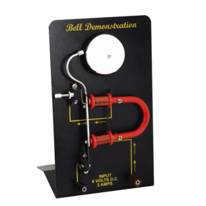
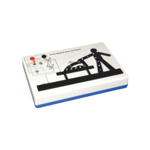
This apparatus is an effective demonstration of how the earth wire and fuse act together to protect both the user and the appliance.
When the appliance is connected correctly and the LEDs in the appliance will illuminate to show the appliance is working.
A fault is then demonstrated by swapping the live wire from inside the appliance to the case to show either the fuse melts (protecting the user and appliance) or in the case of no earth wire, the LEDs illuminate to indicate the passage of current through the person to ground.
The fuse is easily visible and can be seen to ‘blow’ when a fault occurs.The unit is supplied with 10 m of fuse wire and full instructions.
A 12 V DC power supply is required.
Connections are made via 4 mm shrouded sockets.
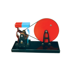
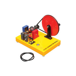
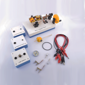
The dynamo model is mounted on a base with a driving wheel.
Output is through 4 mm sockets and a low voltage bulb is also provided as a simple output indicator.
Generates both AC and DC.
When the two brushes of the generator are put in the two ends of the commutator, the output is an AC.
When the brushes are put in the middle of the commutator, the output is a DC.
Includes Instructions.
To distinguish between the conductors and insulators.
Kit contains five strips of different material (wood, acrylic, copper brass and aluminium), one lamp and one 9 V battery mounted on plastic base.
This motor-generator set gives students an insight into the physical and technical relationships on which electric motors, generators and transformers are based.
The modular system allows to set up different function models without tools: Various DC motors Series and shunt motor Synchronous motor DC generator and alternator Transformer.
This set allows the performance of 10 student experiments about the following topics:
Magnetic field of a coil
Conversion of electrical energy into kinetic energy
Commutator
Direct current motor
Synchronous motor
Series and shunt-wound motors
Electromagnetic induction
The electrical generator
Engine-generator
Transformer
This heavy duty demountable transformer can be used for the study of transformertheory and many other alternating current phenomena.
This kit consists of:
1. A magnetic circuit made of highly permeable U shape metal sheet, which can be closed using two clamps with tightening screws.
2. Section: 40 x 40 mm with 150 mm length and 170 mm height.
3. One coil of 6000 turns with maximum current of 0.2 A. Intermediary coil of 2000 turns output.
4. One coil of 600 turns with maximum current of 2.5 A, which is mainly used to create the primary of transformer.
5. One coil of 1200 turns with maximum current of 1.25 A, fitted with intermediary 400 and 800 turns outputs.
6. One coil of 72 turns with maximum current of 12 A, fitted with intermediary 6, 30, 54 and 66 turns outputs.
7. Power supply cable.
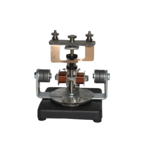
The motor consists of a two pole armature mounted between the ends of two bar magnets.
The armature has a two section commutator and a pair of slip-rings on its shaft and is so constructed that the wire cannot slip off the iron core.
The upper bearing and brushes for the commutator are mounted on a strong upright.
Separate brushes are provided for the commutator and for slip rings and each are connected to a terminal.
The magnets are held in position by thumb screws.


Reviews
There are no reviews yet.