Comprising 1 welding coil of 5 turns on former with insulated handle and short-circuiting pins,1 annular melting trough with insulated handle to show heating by induction,1 jumping ring which is thrown clear when primary current is started and a floating ring which remains freely suspended when primary current is flowing.
For Westminster Electromagnetic Kit giving 1 V full wave rectified DC and 1 V / 2 V AC outputs at 8 A max.
The circuit diagram is printed on the top panel which also carries mains switch, light indicator and output sockets for DC and AC With 1.5 meter mains detachable cable.
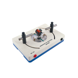
With this simple electric motor model students can investigate the relationship between voltage supplied to rotor and polarity / position of magnets.
On applying 6V DC to 4mm sockets, the rotor will begin to rotate across its vertical axis.
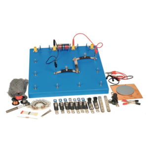
Enables students to investigate nature and properties of electricity by using simple circuits which are easily constructed on a base board.
The connector system uses P.C.B. strips with cut-out sections whose ends can easily be inserted in spring terminals, ensuring low contact resistance and ease of connection.
The kit consists of :
1. Baseboard, plastic, with spring terminals and three battery holders. (1)
2. Batteries. (3)
3. Lamps 1.25 V MES. (10)
4. Lamp holders mounted on PCB connectors. (6)
5. Plain connector PCBs. (10)
6. Wire wound potentiometer with crocodile clip connections. (1)
7. Silicon diode. (1)
8. Resistor 3.9 ohm 2.5 W (1)
9. Pair Leads, red, with crocodile clip at each end. (1)
10. Pair Leads, black, with crocodile clip at each end (1)
11. Pair Leads, yellow, with crocodile clips at each end. (1)
12. Switches mounted on PCB. connectors (2)
13. PVC rod 15 cm long (1)
14. Soft iron nails, 5 cm long (2)
15. Bare copper wire, swg 20 (2 m)
16. Bare eureka wire, swg 34 (2 m)
17. Plastic covered copper wire (2 m)
18. Electrode support (1)
19. Pencil lead electrodes (10)
20. Sheet copper foil, 150 mm square (1)
21. Pack Steel wool (1)
22. Instruction manual in English. (1)
Students can explore how a simple electric motor works by doing a series of investigations.
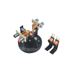
This St. Louis motor can be adjusted so students can study the effect of voltage and position of the brushes on the commutator.
The motor consists of a two pole DC armature. The brush holder, with two heavy binding post terminals, can be rotated for experiments.
The permanent bar magnets, supported by clamps, can be adjusted to the desired location.
This apparatus requires 4 D cell batteries with holder (not included) or a power supply and two connecting leads (not included).


































Reviews
There are no reviews yet.