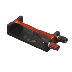
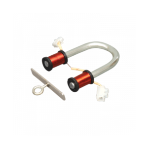
Plastic bobbin with 2, 50 and 500 turns of insulated copper wire and rotatable on vertical axis is mounted on a moulded plastic base, with leveling screws and four terminals, with magnetometer mounted at the center of the bobbin.
This demonstrates the action of electric current on a magnet.
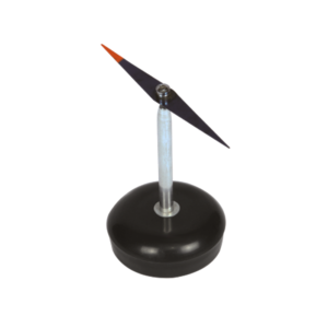
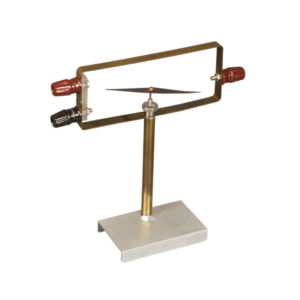
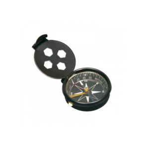
A cobalt steel needle with agate bearing supported by pivot is mounted on a plastic base and surrounded by rectangular frame fitted with terminals.
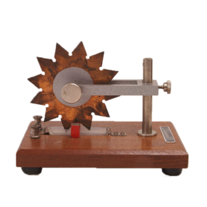
This apparatus spins an electrically charged brass wheel spin, without the aid of a motor.
When the wheel electrified by a voltage source (battery), the slotted brass disc sets up eddy currents throughout the structure.
This electricity is then attracted to 4 strong neodymium magnets, causing the wheel to spin.
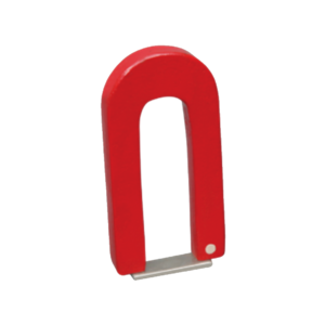
Comprising iron U-shaped core of circular section, with armature and carrying hook.
Wounded with insulated copper wire and provided with connectors for use on 4-6 volts D.C.


Reviews
There are no reviews yet.