Apparatus is designed primarily for demonstration of the basic principles of transformers.
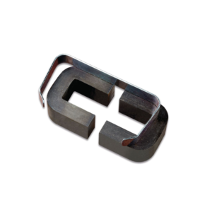
It consists of a laminated U-core with laminated I-core, both with 32 x 25 mm cross section to form a closed core of size 102 x 127 mm.
Heavy aluminium alloy stand with removable clamping rods, 2 pole pieces, each 65 x 30 x 25 mm with one end cone shaped, to accept support rod and shading ring.
Poles also have a hole drilled through lengthwise to take a light beam. 300 turns 600 turns 1200 turns 3600 turns 12000 turns
Designed to demonstrate to implement and applications of electrical, electronic devices and simple circuits. These modules are fitted with 4 mm sockets.
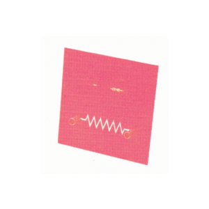
Components are directly mounted on printed PCB with diagram.Various modules are available as following Resistor
LDR
LED
Push Switch
Motor
Reed Relay
Reed Switch
Relay Nand Gate
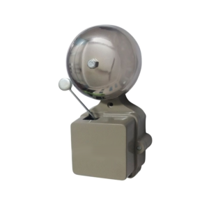
Buzzer
Thermistor
Lamp Holder
Single Pole Double Throw Switch
Electromagnet
Power Transistor
A simple kit for students to gain insight into field poles, armatures and switches, one mounting base, two coils of insulated wire , field pole, mounting bracket, two armature halves, one piece of insulating tubing, motor shaft, two commutator insulators, two bronze wire brushes, two shaft supports, four paper fasteners, a AA battery holder and 6 each of screws and nuts.
Requires one AA battery, not supplied, with assembly instructions.
For Westminster Electromagnetic Kit giving 1 V full wave rectified DC and 1 V / 2 V AC outputs at 8 A max.
The circuit diagram is printed on the top panel which also carries mains switch, light indicator and output sockets for DC and AC With 1.5 meter mains detachable cable.
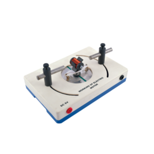
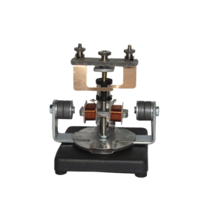
With this simple electric motor model students can investigate the relationship between voltage supplied to rotor and polarity / position of magnets.
On applying 6V DC to 4mm sockets, the rotor will begin to rotate across its vertical axis.
The motor consists of a two pole armature mounted between the ends of two bar magnets.
The armature has a two section commutator and a pair of slip-rings on its shaft and is so constructed that the wire cannot slip off the iron core.
The upper bearing and brushes for the commutator are mounted on a strong upright.
Separate brushes are provided for the commutator and for slip rings and each are connected to a terminal.
The magnets are held in position by thumb screws.


































Reviews
There are no reviews yet.