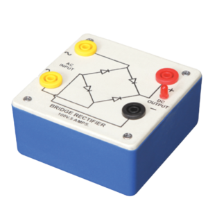
Bridge Rectifier is made of four diodes connected in a bridge circuit. It is housed in a plastic moulded box. This bridge rectifier converts alternating current (AC) into direct current (DC). It provides the same output polarity for either input polarity. All the electronic devices require direct current, so bridge rectifiers are used inside the power supplies of almost all electronic equipment. For the easy understanding of the internal circuitry, the circuit diagram is printed on the box.
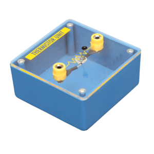
Mounted on transparent covered base for easy demonstration. Diagram and two sockets are provided for use with some circuit. Thermistor is mounted above the base to avoid the damage from heat.
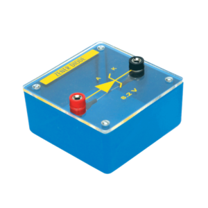
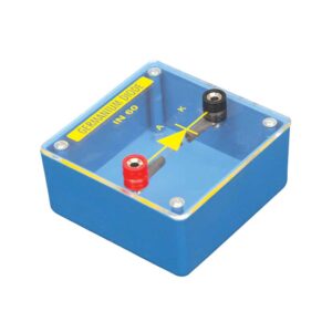
Diode mounted on transparent covered base for maximum visibility to students. Two four mm sockets one red and one black are provided for easy connections.
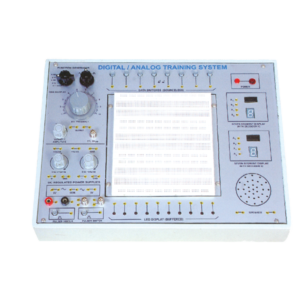
Solderless Breadboard has 1680 tie points. Provided with 2 Terminal strips and 4 Distribution strips. Built in DC Regulated Power Supply. DC Supply ± 5V/ 1 Amp. 0 to ± 15V DC (Variable), 1 Amp. Built-in Function Generator. . Waveform : Sine, Square and Triangle (with selector switch),
Frequency : 1 – 100 Hz Variable
Amplitude : Variable up to 10 V, TTL 5V p-p
Data Switches (Bounceless) – 8 No.
LED Display (buffered) – 10 No.
Clock Pulsar – 2 No.
Seven Segment Display with Decoder IC 7447 – 2 No.
Speaker 2.5 Dia. with sockets – 1 No.
BNC Plug with 2 mm Sockets – 2 No.
4 mm socket connected with 2 mm sockets – 2 No.
Interconnection leads having 2 mm plugs at one end – 10 No.
Interconnection leads having 4 mm plugs at both end – 10 No.
22 SWG Hook Up Wire of 20 cm length – 100 No.
Comprehensive User’s Manual – 1 No.
Input 220 V, 50 Hz. AC with On/Off indicator.


































Reviews
There are no reviews yet.