Instrument is design to demonstrate the method to transmit signals via. Electromagnetic transmission. It is still used in radio system to transmit audio signal although it has lesser in popularity compared to FM (Frequency Modulation) due to its lower signal to noise ratio.
Technical Specification :-
1. I C based DC regulated Power Supply ±12 V / 500 mA.
2. Audio frequency 1 KHz / 0-2 Vpp for modulating signal 455 KHz / 2.5 Vpp approx. for Carrier Frequency.
Objective : To study Efficiency and Ripple factor in case of Half wave, Full wave and Bridge rectifier on application of load and filters.
Features : Instrument comprises of AC Power Supply, 3 meters to measure Output Voltage, Output Current and ripple factor on electronic AC Voltmeter, 4 PN Junction Diodes, Filter Circuit kit, load Resistances selectable using bandswitch and all important connections points at 4mm Sockets.
Optional Acc : Digital AC millivoltmeter.
Trainer consisting of Power Supply of +5 V / ±12 V (each of 250 mA), Silicon, Germanium diodes, Zeners, PNP and NPN Transistors, FET, One speaker, 12 different values of carbon film resistances of ¼ W, ½ W and 1 W. 12 assorted values of capacitors from 100 pF to 1000 ?F, Integrated Circuit (IC) Base and IC 74LS00 1 No. each. LED, LDR, Photo diode, Solar Cell Logic Switches (4 No.) and LED Indicators (4 No.) etc., 2 mm Interconnection Leads -10 No. and Comprehensive User’s Manual
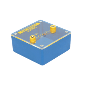
Bridge rectifier is designed with four LEDs internally arranged in bridge pattern fitted inside a plastic moulded case. Two LED’s are red and two LED’s are green. This device is used to demonstrate the functioning of a bridge rectifier, i.e., to convert alternating current (AC) into direct current (DC). Two yellow sockets are used for AC input. Two sockets, one red and one black, are used for DC output. For the easy understanding of the internal circuitry, the circuit diagram is printed on the box.
Objective : To plot Frequency Vs. Current Characteristics of LCR circuit when connected in series or in parallel.
Features : Instrument comprises of 3 Resistances, 3 Capacitors and 1 Inductance connected inside and connections brought out at Sockets. 2 AC moving coil meters to measure voltage and current.
Optional Acc. : Audio Frequency Function Generator
Each module is housed in a plastic box 90 x 90 x 30 mm and is provided with a circuit diagram on the panel. It has necessary input and output sockets. The socket stacking system allows addition of as many modules as desired, designed to work on 6V D. C.


Reviews
There are no reviews yet.