Objective:
To construct an optical transmitter and transmission of signal through Fiber Optics Cable. To construct an Optical Receiver and study the Attenuation of Signal when transmitted from Transmitter to Receiver end. Analog and Digital link can also be studied as this unit is complete with Sine and Square Waves. Bending losses can also be studied.
Features:
Instrument comprises of Microphone Preamplifier stages consists of MIC (Microphone), Preamplifier and Amplifier (Voice is converted to electrical signal and then amplified) and fed to LED (Transmitter) and then through fibre cable, signal is sent to Photodetector (Transistor) and again amplifier and output is sent to Speaker Unit. Power Supply of +6 VDC is used in Amplifier ckt. 2 No. Fiber Optics cables are provided (one of them is 50 cm long and the other is 100 cm long). One more fiber cable of 50mm length having connector at one end is also provided. Connectors a both end of fiber cable are provided for insertion in sockets provided on the front panel. Bending losses can also be studied in long wire.
Standard: MIC with 2 meter long lead and a Speaker 4, 4 ohm are mounted in a vertical box.
Accuracy: with 1 meter long connecting leads. 2 No. Fiber optic cable having length of 50 cm and 100 cm are provided.
Optional : Digital multimeter (3 1/2 Digit, Big size Display) This model also include Digital Multimeter and wooden frame for measurement of Numerical aperture i.e. complete in all respect including facility for measurement of numerical aperture.
Solderless Breadboard has 1680 tie points. Provided with 2 Terminal strips and 4 Distribution strips. Built in DC Regulated Power Supply. DC Supply ± 5V/ 1 Amp. 0 to ± 15V DC (Variable), 1 Amp. Built-in Function Generator. . Waveform : Sine, Square and Triangle (with selector switch),
Frequency : 1 – 100 Hz Variable
Amplitude : Variable up to 10 V, TTL 5V p-p
Data Switches (Bounceless) – 8 No.
LED Display (buffered) – 10 No.
Clock Pulsar – 2 No.
Seven Segment Display with Decoder IC 7447 – 2 No.
Speaker 2.5 Dia. with sockets – 1 No.
BNC Plug with 2 mm Sockets – 2 No.
4 mm socket connected with 2 mm sockets – 2 No.
Interconnection leads having 2 mm plugs at one end – 10 No.
Interconnection leads having 4 mm plugs at both end – 10 No.
22 SWG Hook Up Wire of 20 cm length – 100 No.
Comprehensive User’s Manual – 1 No.
Input 220 V, 50 Hz. AC with On/Off indicator.
Trainer consisting of Power Supply of +5 V / ±12 V (each of 250 mA), Silicon, Germanium diodes, Zeners, PNP and NPN Transistors, FET, One speaker, 12 different values of carbon film resistances of ¼ W, ½ W and 1 W. 12 assorted values of capacitors from 100 pF to 1000 ?F, Integrated Circuit (IC) Base and IC 74LS00 1 No. each. LED, LDR, Photo diode, Solar Cell Logic Switches (4 No.) and LED Indicators (4 No.) etc., 2 mm Interconnection Leads -10 No. and Comprehensive User’s Manual
Objective : To plot Frequency Vs. Current Characteristics of LCR circuit when connected in series or in parallel.
Features : Instrument comprises of 3 Resistances, 3 Capacitors and 1 Inductance connected inside and connections brought out at Sockets. 2 AC moving coil meters to measure voltage and current.
Optional Acc. : Audio Frequency Function Generator
Lorem Ipsum is simply dummy text of the printing and typesetting industry. Lorem Ipsum has been the industry's standard dummy text ever since the 1500s, when an unknown printer took a galley of type and scrambled it to make a type specimen book. It has survived not only five centuries, but also the leap into electronic typesetting, remaining essentially unchanged. It was popularised in the 1960s with the release of Letraset sheets containing Lorem Ipsum passages, and more recently with desktop publishing software like Aldus PageMaker including versions of Lorem Ipsum.
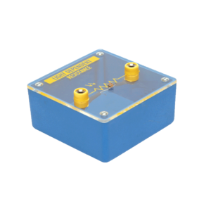
Mounted on transparent covered base for easy demonstration. Diagram and two sockets are provided for use with some circuit. Thermistor is mounted above the base to avoid the damage from heat.
Reviews
There are no reviews yet.