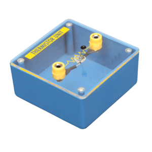
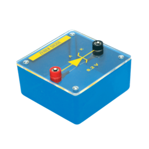
Mounted on transparent covered base for easy demonstration. Diagram and two sockets are provided for use with some circuit. Thermistor is mounted above the base to avoid the damage from heat.
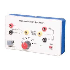
Instrumentation amplifier is a switched gain precision operation amplifier. This is used for precise and accurate, low noise differential signal acquisition. 4mm sockets are used for the input signal. It can be interfaced with a wide range of sensors. It can take small voltage changes from a sensor and make those changes large enough to be measured using CRO. It is not able to drive a low impedance load such as a loudspeaker or relay. The output can be read on CRO. Digital multimeter may also be used to read the output. With switched gain of 5 to 1000, it can handle signal inputs over a very wide range making it suitable for almost all applications.
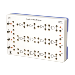
Logic Gates Trainer has been designed to study logic gates and applications. This trainer board is designed to verify the truth table of various logic functions, to prove De-Morgan’s theorem, Half adder and Full adder by using logic gates. The board is absolutely self-contained and requires no additional apparatus. 12 V / 1 A DC adaptor is required to operate it.
This Trainer Consist of :
1. Regulated power supply of ± 12 V / 250 mA.
2. Variable 0 to ±5 V / 250 mA.
3. Sine wave oscillation of 1 KHz.
4. Digital Voltmeter of 0-20 V DC, LCD display, 3 ½ Digit.
5. Functional diagram of IC 741 is printed with 2 mm sockets.
6. One extra 8 pin IC Base with 2 mm sockets.
7. Potentiometer of 10K Ohms.
8. Required Resistance and Capacitances mounted on board.
9. Interconnection Leads and Manual to perform 15 experiments on IC741 e.g. inverting, non-inverting, summing, difference, multiplier, differentiator, integrator etc.
A common anode seven segment module is fitted on a board with 8 bit dip switch to control the each segment of seven segment LED display. The inputs A-D of a display driver are connected to the binary coded decimal (BCD) outputs from a decade counter. A network of logic gates inside the display driver makes its outputs a-g become high or low as appropriate to light the required segments a-g of a seven segment display. A resistor is required in series with each segment to protect the LEDs


































Reviews
There are no reviews yet.