Description
Verification Clarke S Maxwell Reciprocal Theorem
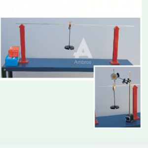
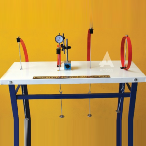
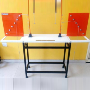
Apparatus for Verification of Clarke’s Maxwell Reciprocal Theorem
Apparatus consist of a mild steel beam 100cm long and 1.25cm x 4mm in cross section with graduations at every 10cm along the length. It should be supported on two knife edge supports 70cm apart with a 30cm overhang on one side. Reciprocal theorem can be verified by direct measurements of the deflections of various points with the help of a dial gauge due to a load placed at the reciprocal points. A dial gauge with 25mm travel (with a magnetic base) should be supplied with the apparatus. Apparatus to be supplied should be complete with a supporting stand and a set of weights.
Experimental Capabilities: To verify Clerk’s Maxwell reciprocal theorem by means of a mild steel be
Category: Structural Mechanics Lab
Reviews (0)
Be the first to review “Verification Clarke S Maxwell Reciprocal Theorem” Cancel reply
Related products
Elastically Coupled Beam Apparatus
Apparatus consists of a three parallel bar suspension system with elastic beam at their upper and lower ends. The upper ends of the two outer suspension rods are tied to a vertical wooden board while central suspension rod may be tied to the centre of another elastic beam supported at two outer ends only. Mild steel Apparatus to be supplied should be complete with a supporting stand and a set of weights.
Torsion Of Rods Apparatus
INTRODUCTION:
A torsion test is quite instrumental in determining the value of modulus of rigidity of a metallic specimen. The value of modulus of rigidity can be found out thought observations made during the experiment by using the torsion equation.APPARATUS:
1. A torsion testing machine. 2. Twist meter for measuring angles of twist 3. A steel rule and Vernier Caliper or micrometerCurved Member Apparatus
Apparatus consists of a steel bar which is used to make the different curved members Viz. circle, semicircle with straight arm, a quadrant of a circle and quadrant of a circle with straight arm. The bottom ends of the members are fixed to the base. Under the application of load at free end, its horizontal and vertical deflection can be measured with the help of dial gauges. A dial gauge with 25mm travel (with a magnetic base) is supplied with the apparatus. Apparatus to be supplied should be complete with a supporting stand and a set of weights.
Experimental Capabilities: Apparatus is supplied complete with a supporting stand and a set of weights.
Pinned Joint Model
SPECIFICATION:
Model consists of hinged. Model will be able to demonstrate the qualitative behavior of the truss under load. As are very flexible, a compression members will easily it`s bucking i.e. It will curve of plain. The tension member however remains straight and tight. The student will therefore have a visual picture of the type of stresses i.e. Compressive or tensile that member of truss will carry under various positive of the load. In case of pinned joint truss, the student will be able to observe that angle between members at each joint undergo a small change.Deflection Of Truss Apparatus
Apparatus consist of 4 panels of a PRATT steel truss, each panel being 40cm in horizontal direction and 30cm in vertical direction. Load can be applied on each panel point. All tension members should be provided with detachable springs so as to obtain appreciable deformation of the member. Direction of the diagonal members may be changed. Apparatus can be used to illustrate visually the nature of forces set up in various members of the Truss. Apparatus to be supplied should be complete with a supporting stand and a set of weights.
Experimental Capabilities: Apparatus is supplied complete with a supporting stand and a set of weights.
Unsymmetrical Bending Apparatus
DESCRIPTION:
Apparatus consist of an angle of size 1” x 1” x 1/8” or in equivalent metric units of length 80cm is tied as a cantilever beam. The beam is fixed at one end such that the rotation of 450 intervals can be given and clamped such that the principal axis of its cross-section may be inclined at any angle with the horizontal and vertical planes. Also arrangement is provided to apply vertical load at the free end of the cantilever and to measure horizontal and vertical deflection of the free end. A dial gauge with magnetic base is supplied with the apparatus.EXPERIMENT MANUAL:
• To study the behavior of a cantilever beam under symmetrical and unsymmetrical bending. • Using a Dial gauge shown a increasing and decreasing of heights.Three Hinged Arch Apparatus
The mild steel model has a span of 100cm and rise 25cm, with hinges at supports and crown. One of the ends should rests on rollers. Along the horizontal span of the arch various points are marked at equidistant for the application of load. This being a statically determinate structure, the horizontal thrust developed under the action of any load system can be theoretically calculated and will also be measured directly by neutralizing the outward movement of the roller end. A dial gauge with 25mm travel (with magnetic base) may be supplied with the apparatus. Apparatus to be supplied should be complete with a supporting stand and a set of weights.
Reviews
There are no reviews yet.