[contact-form-7 404 "Not Found"]
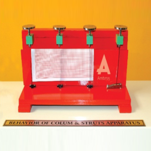
Behaviour Of Column Struts Apparatus
Apparatus consist of four spring steel columns which are put along a vertical wooden board. These four columns have different end conditions as below:
1. Both ends pinned
2. Both ends fixed
3. One end pinned and other fixed
4. One end fixed and other end free
Apparatus to be supplied should be complete with a supporting stand and a set of weights.
Bending Moment & Shear Force Apparatus
INTRODUCTION:
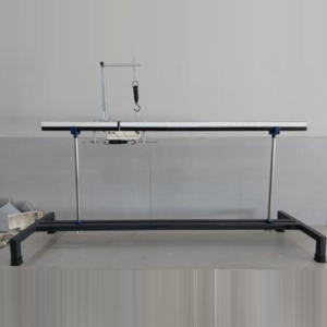
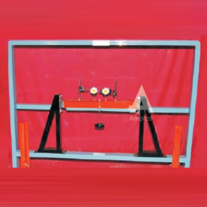
Shear Forces occurs when two parallel forces act out of alignment with each other. For example, in a large boiler made from sections of sheet metal plate riveted together, there is an equal and opposite force exerted on the rivets, owing to the expansion and contraction of the plates. Bending Moments are rotational forces within the beam that cause bending. At any point within a beam, the Bending Moment is the sum of: each external force multiplied by the distance that is perpendicular to the direction of the force.EXPERIMENT MANUAL:
1. To verify the Shear force a cross-section of the beam. 2. To verify the bending moment in cross–section of beam with a flexure condition.APPARTUS SPECIFICATION:
1. Dimensions : 158 cm X 45cm X (h)60cm 2. Total Beam Length : 160 cm with flexure 3. Width of Beam : 5 cm 4. Distance of Length in between : 5 cm 5. Height of beam : 36 mm 6. No. of Hanger for weights : 3 7. No. of Spring Balance : 2 (of 10kg) 8. Total Weight of Apparatus : 13.1 kgACCESSORY REQUIRES:
1. Shear force apparatus 2. Bending Moment Apparatus 3. Hangers 4. Weights 5. Two Spring balances – 10kgsCurved Member Apparatus
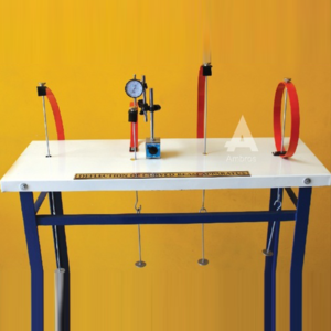
Apparatus consists of a steel bar which is used to make the different curved members Viz. circle, semicircle with straight arm, a quadrant of a circle and quadrant of a circle with straight arm. The bottom ends of the members are fixed to the base. Under the application of load at free end, its horizontal and vertical deflection can be measured with the help of dial gauges. A dial gauge with 25mm travel (with a magnetic base) is supplied with the apparatus. Apparatus to be supplied should be complete with a supporting stand and a set of weights.
Experimental Capabilities: Apparatus is supplied complete with a supporting stand and a set of weights.
Deflection Of Truss Apparatus
Apparatus consist of 4 panels of a PRATT steel truss, each panel being 40cm in horizontal direction and 30cm in vertical direction. Load can be applied on each panel point. All tension members should be provided with detachable springs so as to obtain appreciable deformation of the member. Direction of the diagonal members may be changed. Apparatus can be used to illustrate visually the nature of forces set up in various members of the Truss. Apparatus to be supplied should be complete with a supporting stand and a set of weights.
Experimental Capabilities: Apparatus is supplied complete with a supporting stand and a set of weights.
Elastic Properties Of Deflected Beam Apparatus
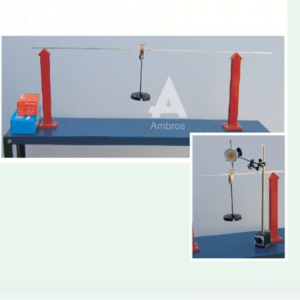
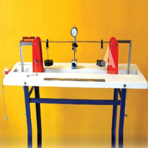
Apparatus consists of a mild steel beam 2.5cm x 3mm in cross section and 100cm long, pinned to two supports 70cm apart situated symmetrically. One of the ends can be fixed or given a known slope by applying a known moment at the end with the help of suspended loads. At the other end also a known moment can be applied. Vertical loads can be applied at various points along the span of the beam. A dial gauge with 25mm travel (with a magnetic base) may be supplied with the apparatus. Apparatus to be supplied should be complete with a supporting stand and a set of weights
Elastically Coupled Beam Apparatus
Apparatus consists of a three parallel bar suspension system with elastic beam at their upper and lower ends. The upper ends of the two outer suspension rods are tied to a vertical wooden board while central suspension rod may be tied to the centre of another elastic beam supported at two outer ends only. Mild steel Apparatus to be supplied should be complete with a supporting stand and a set of weights.
Pinned Joint Model
SPECIFICATION:
Model consists of hinged. Model will be able to demonstrate the qualitative behavior of the truss under load. As are very flexible, a compression members will easily it`s bucking i.e. It will curve of plain. The tension member however remains straight and tight. The student will therefore have a visual picture of the type of stresses i.e. Compressive or tensile that member of truss will carry under various positive of the load. In case of pinned joint truss, the student will be able to observe that angle between members at each joint undergo a small change.Portal Frame Apparatus
DESCRIPTION:
Portal Frames used for the measurement of horizontal reaction are made stiffer by using M. S. flats rectangular cross section (10mm thick and 40mm wide). All are true to shape. The ends can be other fixed of hinged as desired. The end at which horizontal reaction, is to be measured, is provided with ball bearing rollers, which easily rolls on a smooth rolling platform. At the roller end a chord is attached which is connected further to spring balance. The spring balance records the horizontal reaction, for the measurement of slope and deflection. Both the columns of the portal frame can be clamped (fixed) or pivoted (hinged) and required.EXPERIMENT:
• To study the behavior of a portal frame under different end conditions.TECHNICAL SPECIFICATION:
• Apparatus made up of M.S. plate of rectangular section of 3mm thick x 40cm wide. • Frame is provided with a provision to achieve different end conditions viz. hinged, roller & fixed. • The size of portal will be 40cm x 60cm. Portal may also have a provision for pulley arrangement and hook arrangement for horizontal loading at different positions. • Apparatus is to be supplied complete with a supporting stand and a set of weights • Electronic load cells, displacement cell and Electronic Control Unit (ECU) provided with apparatus. • Software for digital calculations to easily performs by students.OPTIONAL ACCESSORIES:
• PC/Laptop Set.Redundant Joint Apparatus
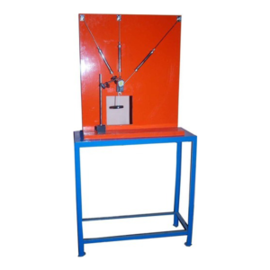
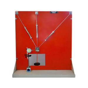
Apparatus consists of three suspension members (spring balances) of different stiffness, which are jointed at a point to form the redundant joint. The upper end of the suspension members being tied in a position to a vertical wooden board. Arrangement is provided to apply a vertical load at the joint and to measure its horizontal and vertical displacement on a paper and also elongations and forces in the suspension members by the help of dial gauges. Dial gauges with magnetic base are provided with the apparatus.
EXPERIMENT:
Comparison of experimental and theoretical results of forces in the members and the component displacement of the loaded joint D of a three bar suspension system for vertical loads.REQUIRED ACCESSORIES:
• Redundant Joint Apparatus • Dial Gauge : 1 No. • Magnetic Base : 1 No. • Hangers : 1 Nos. • Weight of 500gm : As Per requirement.Shear Centre Apparatus
Apparatus consists of sturdy base frame and Channel, Equal angle, Semicircle and Z-Section are supplied with apparatus. Standard length of each of the four sections in M. S. is supplied. Each is provided with end clamp for fixing to the rigid bracket. A special load hanger is provided so as to change the load position so that with the help of two dial-gauges, the vertical plane of Shear-centre for the particular section can be determined.
RANGE OF EXPERIMENTS:
1. Determination of the vertical plane of shear center for different cross sections commonly used for structuresSuspension Bridge Apparatus
DESCRIPTION:
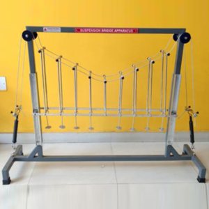
Cables are frequently used to support loads over large spans such as cable stayed for suspension bridges, cable car systems and stadium roof. They are used extensively for permanent guys on structures such as microwave towers and derricks. They are also used for temporary guys during erection. The only force in a cable is direct tension. They are too flexible to carry any moment. A cable is used to carry concentrated loads, uniformly distributed load along its length and uniformly distributed load along the horizontal span. It takes the shape of a polygon under concentrated loads, a catenary under uniform load along its length (such as its own weight), and a parabola under uniform load along the horizontal span.EXPERIMENT:
• Study the Extension of each spring Balance Left & Right Both. • Study of the effect of a point loadTECHNICAL SPECIFICATION:
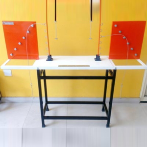
• Apparatus Consists of two mild steel cables 0.5cm diameter in cross section and 150cm long, pinned to two supports 90cm apart situated symmetrically. • One of the ends can be converted to a roller by applying a known load at the end with the help of suspended pulley system. • Vertical loads can be applied at various points along the span of the beam. • A dial gauge with 25mm travel (with a magnetic base) is to be supplied with the apparatus complete with a supporting stand and a set of weights.Three Hinged Arch Apparatus
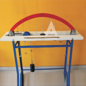
The mild steel model has a span of 100cm and rise 25cm, with hinges at supports and crown. One of the ends should rests on rollers. Along the horizontal span of the arch various points are marked at equidistant for the application of load. This being a statically determinate structure, the horizontal thrust developed under the action of any load system can be theoretically calculated and will also be measured directly by neutralizing the outward movement of the roller end. A dial gauge with 25mm travel (with magnetic base) may be supplied with the apparatus. Apparatus to be supplied should be complete with a supporting stand and a set of weights.
