[contact-form-7 404 "Not Found"]
Lathe Tool Dynamometers
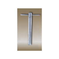
This is a strain gauge type two component lathe tool dynamometer designed to measure vertical and horizontal forces on the while orthogonal cutting process. The unit is in two parts one is mechanical sensing unit or tool holder, which can mounted on the top of the Ross slide after removing swivel base and compound slide of a lathe and digital force indicator. With this Dynamometer student can study the change in these forces by varying Speed, Cut and Feed.
FEATURES:
1.Rigid in construction 2.Sensitive transuding and amplifying system for accuracy in force measurement. 3.Compact Digital force indicator. 4.Use of cutting fluid during operation is possible.SCOPE OF SUPPLY:
1.Mechanical sensing unit or Tool Holder with string gauges. With H.S.S. tool of ½ “ size. 2.Control panel housing digital force indicator to measure two forces simuletensiously, balancing potentiometers, connoting cable. 3.Necessary switches, fuses and polycarbonate front plate. Range o to 500 Kg. 4.Centre Height, P.C.D.of clamping bolt size, clamping Bolt size. Three component lathe tool dynometer is also available.Milling Tool Dynamometers
This is a simple and essay to understand set up introduce by sharp techno systems to study the behavior of cutting forces during milling operation in three directions. With this unit students can evaluate cutting depth, speed and feed. The unit works on standard method of octagonal ring with strain gauges. It is in to part one mechanical rings sandwiched between two M.S. plate with strain gauges fixed on it. This set of octagonal rings transmits the relevant data to the force indicator during milling operation.
FEATURES
1.Rigid construction & Compact Unit. 2.Assessment of cutting forces by giving due consideration to various parameters like depth of cut, material, cut, material, speed and feed. 3.Eassy in handling & Digital force indicators to measure three forces simuleniously.SPECIFICATIONS-
1.Mechanical sencing unit with set of octagonal rings and strain gauges. 2.Three channel digital force indicator with balancing potentiometers and polycarbonate front plate. 3.Range of force measurement in coordinate direction – 0 to 500 kg. 4.Over all size of mechanical unit- 300 x 300 mm.SERVICE REQUIRED
1.Necessary Milling Machine with automatic feed arrangement and tooling 2.230 volts, single phase, 50 Hz stabilized power supply.Motorised Governor Apparatus
The unit consists of a base upon which the bearing holders and driving motor are bearing can be fitted in a holders to end conditions for test shafts, viz. Both end fixed and one end free, one end fixed. A Variac provided control of driving motor. The unit demonstrates the phenomenon of whirling of shafts with single rotor. As the test is destructive, after the test cannot be used, hence the unit only demonstrates the principle.
However, results obtained are closer to theory, as compared to those with bare shafts. Also, It can be demonstrated that, after passing whirling speed, shaft again starts running true.
SPECIFICATIONS OF MOTORISED GOVERNOR APPARATUS:
1.Test shaft – 4.75 mm, 6.35 mm and 7.9 mm – 2 each. 2.Bearing to provided end conditions, (a) Both ends fixed, (b) One end fixed and one end free. 3.Drive motor 1/8 HP, 1500 rpm with control arrangement. 4.The whole unit is mounted on a sturdy base. 5.Rotor for each shaft of suitable size. 6.A technical manual accompanies the unit.SERVICES REQUIRE FOR MOTORISED GOVERNOR APPARATUS:
Floor space area of 2m. X 1m. at working height. 230V, 15 A, AC electric supply connection.Motorised Gyroscope Apparatus
The apparatus consists of a rotor mounted in bearings. This rotor is free to rotate about
(i) Its own axis i.e. axis of spin.
(ii) Axis of precession.
(iii) Axis of gyroscopic couple.
The rotor is connected to the variable speed motor. The weight of the motor is balanced by another weight, which is on either side of the rotor. By putting weights on the weight platform torque can be supplied to rotor, which is also called gyroscopic couple.
SPECIFICATIONS OF MOTORISED GYROSCOPE APPARATUS:
1.Rotor dia. 250mm free about 3 axis of rotation driven by variable speed motor. 2.Dimmerstat to control the motor speed. 3.Stopwatch to measure the angular speed about the axis of precession. 4.Weights – 0.2 kg, 0.5 kg and 1 kg. 5.A technical manual accompanies the unit.SERVICES REQUIRE FOR MOTORISED GYROSCOPE APPARATUS:
1.220v stabilized AC supply with earthing connection. 2.Bench area – 0.5 x 0.5m at working height. 3.Tachometer for speed measurement (can be supplied at extra cost).Slip Creep Measurement Apparatus
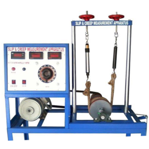
The apparatus consists of a variable speed D.C. Motor, Driving pulley and Driven pulley of equal diameter. The pulleys are mounted on input shaft (Motor shaft) and output shaft. The driven pulley can slide on the base with bearing block to change initial tension in belt. Brake drum is mounted on output shaft helps to measure power output. The motor speed is varied by dimmerstat. A two channel RPM Indicator is provided to measure speeds of driven and driving pullies respectively.
Specifications:
1.D.C. Motor – 1 HP, 1500 RPM, variable speed. 2.Driving & Driven puilies of equal diameters. 3.Brake drum along with spring balance. 4.Fiat Belt of fixed length of following materials – (i)Fabric Belt (ii)Canvas Belt. (iii)Rubber Belt. 5.Belt tightening arrangement. 6.Speed Controller unit. 7.Two Channel digital RPM Indicator. 8.Stroboscope.Experimentation –
1. To measure co-efficient of friction between pulley material and different belt materials. 2. To measure power transmitted with varied belt tensions and plotting graph of (T1 – T2).Tension Characteristics. 3. To measure percentage slip at fixed belt tension by varying load on brake drum and plot graph of (T1-T2) Vs.percentage slip.i.e. Slip Characteristics. Finding a creep zone from graph. 4. To measure belt slip speed and observe the limiting value float at constant speed when the slip just starts.Service Required:
1.230 V.A.C. stabilized power supply 2.Space -. 1.5m x 1.5 m.Static Dynamic Balancing Apparatus
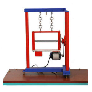
This equipment is designed for carrying out the experiment for balancing a rotation mass system. The apparatus consists ofa stainless steel shaft fixed in a rectangular frame. A set of four blocks with a clamping arrangement is provided. For static balancing, each block is individually clamped on shaft and its relative weight is found out using cord and container system in terms of number of steel balls. For dynamic balancing, a moment polygon is drawn using relative weights and angular and axial position of blocks is determined. The block are clamped on shaft is rotated by a motor to check dynamic balance of the system. The system is provided with angular and longitudinal scales and is suspended with chains for dynamic balancing.
EXPERIMENTS OF STATIC & DYNAMIC BALANCING APPARATUS:-
1. To balance the masses statically and dynamically of a single rotating mass system. 2. To observation of effect of unbalance in a rotating mass system.UTILITIES OF STATIC & DYNAMIC BALANCING APPARATUS:-
Electricity 0.5 kW, 220 V, Single PhaseTECHNICAL SPECIFICATION OF STATIC & DYNAMIC BALANCING APPARATUS:-
1. Drive Motor -- FHP Motor, variable speed, with speed controller 2. Balancing Weight -- 4 Nos. of Stainless Steel with different sized eccentric Mass for varying unbalance 3. Rotating Shaft -- Material Stainless Steel 4. The whole Set-up is well designed and arranged in a good quality painted StructureTool Dynamometers
A machine-tool dynamometer is a multi-component dynamometer that is used to measure forces during the use of the machine tool. Empirical calculations of these forces can be cross-checked and verified experimentally using these machine tool dynamometers.
(1) Milling Tool Dynamometers
(2) Grinder Tool Dynamometers
(3) Lathe Tool Dynamometers
(4) Drilling Tool Dynamometers
Vibration Lab Complete 11 Experiment
The VIBLAB is designed to help in conducting various experiments to illustrate and verify the principles and relations involved in the study of vibrations.
This apparatus enables a comprehensive range of Vibration Experiments to be conducted on single basic framework. The frame is robustly constructed from channel section. The experiments are specially designed for quick and easy assembly on to the framework using a minimum amount of common engineering tools. To reduce changeover time on tube more advanced free and forced vibration experiments, large knurled knobs are used to clamp components on the frame and many components are common to several experiments.
All of the referenced groups of experiments are available separately making it possible to procure them individually & if required to build up a complete set over a period of time.
Specifications:
1.Wide range of experiments. 2.Forced and Free Vibrations. 3.Damped and undamped vibrations. 4.Arrangements for variation of damping. 5.Sturdy storage cabinet. 6.Experiments easily assembled. 7.Covers experiments for undergraduate studies. 8.Scope for student projects.Features:
[I] Pendulum Experiments: 1.Simple Pendulum. 2.Compound Pendulum. 3.Bi-filler Suspension. [II] Longitudinal Vibration Expiariment. 1.Spring Mass System. 2.Eciuivalent Spring Mass study of undarrped 3.System free vibration [III] Torsional Vibration Experiment. 1.Single Rotor Systern. 2.Two Rotor System. 3.Single Rotor with viscous darnping. [IV] Damped Vibration Experiment. 1.Verification of Dukerleys Rule. 2.Forced rotor with viscous damping along with frictional HP Motor Strip chart recorder & control unit. 3.A technical manual accompanies the equipment.Services required:
1.230 V, A.C. stabilized supply along with earthing connection. 2.Bench area 0.5m x 0.5m x 0.5m height. 3.Tachometer to measure the jumping speed, (can be supplied extra)Whirling Of Shaft Apparatus
The unit consists of a main spindle driven by a variable speed motor. Three different governor assemblies can be mounted over the spindle. A with pointer measures the lift of the governor. Students can calculate characteristics of governor at and compare their performance viz. Sensitiveness, stability, governor effort etc.
