Error: Contact form not found.
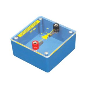
Germanium Diode Unit
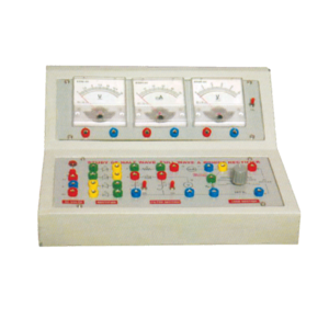
Half Wave / Full Wave And Bridge Rectifier Apparatus
Objective : To study Efficiency and Ripple factor in case of Half wave, Full wave and Bridge rectifier on application of load and filters.
Features : Instrument comprises of AC Power Supply, 3 meters to measure Output Voltage, Output Current and ripple factor on electronic AC Voltmeter, 4 PN Junction Diodes, Filter Circuit kit, load Resistances selectable using bandswitch and all important connections points at 4mm Sockets.
Optional Acc : Digital AC millivoltmeter.
Hall Probe
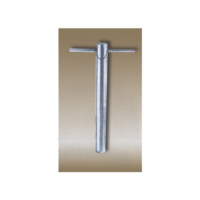
Ge single crystal with four spring-type pressure contacts is mounted on the printed circuit board. Four leads are provided for connections with measuring devices.A zero setting can be done by adjusting the spring contacts with the help of screw driver.
Specifications:
Material: Ge single crystal, n type
Resistivity: 8 – 10 ?-cm
Contacts: Spring type
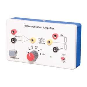
Instrumentation Amplifier
Instrumentation amplifier is a switched gain precision operation amplifier. This is used for precise and accurate, low noise differential signal acquisition. 4mm sockets are used for the input signal. It can be interfaced with a wide range of sensors. It can take small voltage changes from a sensor and make those changes large enough to be measured using CRO. It is not able to drive a low impedance load such as a loudspeaker or relay. The output can be read on CRO. Digital multimeter may also be used to read the output. With switched gain of 5 to 1000, it can handle signal inputs over a very wide range making it suitable for almost all applications.
LCR Resonance Apparatus
Objective : To plot Frequency Vs. Current Characteristics of LCR circuit when connected in series or in parallel.
Features : Instrument comprises of 3 Resistances, 3 Capacitors and 1 Inductance connected inside and connections brought out at Sockets. 2 AC moving coil meters to measure voltage and current.
Optional Acc. : Audio Frequency Function Generator
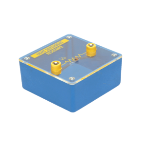
Light Dependent Resistor Unit (LDR)
Linear IC Trainer
This Trainer Consist of :
1. Regulated power supply of ± 12 V / 250 mA.
2. Variable 0 to ±5 V / 250 mA.
3. Sine wave oscillation of 1 KHz.
4. Digital Voltmeter of 0-20 V DC, LCD display, 3 ½ Digit.
5. Functional diagram of IC 741 is printed with 2 mm sockets.
6. One extra 8 pin IC Base with 2 mm sockets.
7. Potentiometer of 10K Ohms.
8. Required Resistance and Capacitances mounted on board.
9. Interconnection Leads and Manual to perform 15 experiments on IC741 e.g. inverting, non-inverting, summing, difference, multiplier, differentiator, integrator etc.
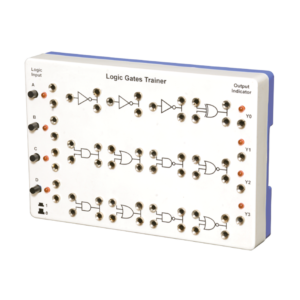
Logic Gates Trainer
Logic Gates Trainer has been designed to study logic gates and applications. This trainer board is designed to verify the truth table of various logic functions, to prove De-Morgan’s theorem, Half adder and Full adder by using logic gates. The board is absolutely self-contained and requires no additional apparatus. 12 V / 1 A DC adaptor is required to operate it.
Micro Controller Development Board
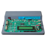
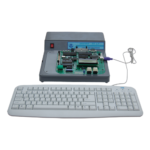
Microcontroller development board is designed to train engineers about the structural design, instructions and utilize the 8051 microcontroller board. A 40 pin ZIF socket for easy insertion of 89 series microcontroller with four 10 Pin FRC connectors is provided on the board. Outputs from I/O port from microcontroller are available on FRC connectors those can be easily connect with different modules. Microcontroller Development Board consists of EEPROM with 4K memory changeable with more RTC DS1307 with 32 KHz crystal with battery backup One 12 V stepper motor with drivers.One 16 x 2 LCD display. 8 Output LED indicators. 4 multiplexed 7-segment display. 8 single bit toggle switch. 4 x 4 matrix keyboard. Single Channel ADC with potentiometer and provision of external inputs RS 232 serial communication. One 12 V DC motor driver.
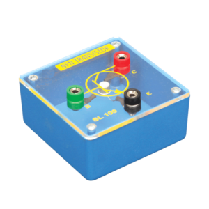
N-P-N Transistor Unit
Numerical System
This panel is used to demonstrate the number systems such as binary, decimal and hexadecimal numbers. Toggle switches used to activate the displays showing the particular number entered. Input may be entered either as decimal or binary numbers with a toggle switch for mode selection. Decimal numbers are shown on a three digit seven segment LED display. 12 V / 2 A DC adaptor is required to operate it.
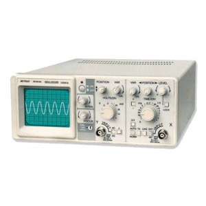
Oscilloscope
This Oscilloscope is corresponding to horizontal with small size. The bandwidth of Y axis is DC 10 MHz and the deflection factor is 5 mV 5 V / div. It can be up to 50 V / div. using with the 10:1 probe. Sweep deflection factor is 0.1 ?s / div.
(1) Single Channel Single Trace Oscilloscope
(2) Bandwidth : 10 MHz
(3) Confirms to EN61010-1 (1993) and EN-IEC61326-1(1997).
(4) Wide measurement
(5) High sensitivity and trigger lock
(6) Sweep switch adopts digital code switch and accuracy
(7) Proper to use in colleges and for engineers and technicians
(8) Deflection factor is 5 mV – 5 V / div in 1-2-5 Sequence in 10 steps
(9) Accuracy: ±5 % (
10) Maximum Input Voltage: 400Vpk
(11) Sweep deflection factor is 0.1 us / div to 0.1 s / div
(12) Accuracy: ±5 %
(13) Trigger Sensitivity: INT:1.5 div EXT:0.3 V
(14) Trigger mode: INT, EXT, LINE, TV
(15) Trigger Sweep Mode: NORM, AUTO, TV. LOCK.
(16) Calibration Signal: 0.5 V Square wave of 1 kHz.
(17) CRT Effective working Area: 8 x 10 div. 1 div = 6 mm.
(18) Auxiliary Power Supply: 220V AC 50Hz
