Error: Contact form not found.
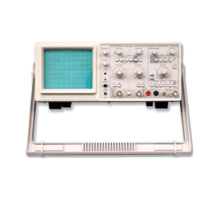
Oscilloscope
This is a portable type of Oscilloscope for two traces. The band width is 0-20 MHz. The instrument is of easy operation with comfortable controls. Its reasonable structure and technology makes it convenient to repair and calibrate.
(1) Dual Trace Dual Channel Oscilloscope with Component Test Facility
(2) Bandwidth : 20 MHz
(3) Full bandwidth sweeping circuit is used in the sweeping system
(4) The flexible and convenient triggering mode has the functions for selecting signals from one channel or triggered by Ext signals
(5) ALT trigger to observe signals from two irrelative channels
(6) The instrument has the functions of TV-H / TV-V synchronization and trigger-lock to observe all kinds of signals stably
(7) From the terminal for trigger input, CH1 and CH2 signals can be output along with the triggering channel to connect the external frequency counter
(8) Y deflection operation : Y1, Y2, ALT, CHOP, ADD, mode X-Y
(9) Vertical Deflection : 5 mV / Div to 20 V / Div in factor 1-2-5 sequence in 12 steps
(10) Rising time : < 18 nS (11) Maximum Input Voltage : 400V (DC + ACp-p) (12) Triggering Source : Y1, Y2, ALT, POWER, EXT (13) Trigger Coupling : AC / DC (EXT), NORM / TV-H, TV-V (14) Horizontal Sweep Mode : AUTO, TRIG, LOCK, SINGLE (15) Sweep time factor : 0.1 uS / div to 0.2 s / div in 1-2-5 sequence in 20 steps (16) Magnification : x10 (17) X-Y Mode input : X-Axis Y1 and Y-Axis Y2 (18) Z Axis minimum input level : TTL Level (19) Component Test Facility (20) Calibration Signal : Square wave of 0.5 V at 1 kHz (21) CTR Display size : 8 cm x 10 cm (22) Auxiliary Power Supply : 220V 50Hz AC
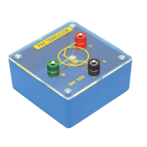
P-N-P Transistor Unit
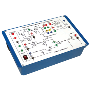
Phase Shift Keying Modulation and Demodulation
This Instrument is design to demonstrate the method to transmit signals via. Electromagnetic transmission and to study the Phase Shift Keying Modulation and Demodulation. Whole instrument is placed in plastic moulded box and 2 mm banana plug leads are provided for modulation and demodulation connections.
Technical Specification:-
1. Fixed Output DC Regulated Power Supplies of ±12 V and ±5 V.
2. Built in Carrier wave Generator (Sine Wave) of 5 Vpp, 22 KHz ± 5% Frequency range with output on sockets.
3. Built in Data Generator using IC 7490 with four modulating signal outputs on sockets.
4. IC TL084 & IC 7486 are using for PSK demodulator.
5. Circuit diagram is printed on the milky white top panel and important connections are brought out on the sockets.
Photon Energy Array
Planck’s Constant
Modern LEDs (light emitting diodes) cover the range from deep blue (440 nm) to infra-red (940 nm). By monitoring the voltage at which each LED just begins to emit light a graph of energy input as a function of light emitted frequency can be plotted and an approximate value of Planck’s constant deduced. Complete with viewing tube but without power supply.
Pulse Width Modulation and Demodulation
This Instrument is design to demonstrate the method to transmit signals via. Electromagnetic transmission and to study the Pulse Width Modulation and Demodulation. Whole instrument is placed in plastic moulded box and 2 mm banana plug leads are provided for modulation and demodulation connections.
Technical Specification:-
1. Built in IC based DC Regulated Power supply ±12 V, +5 V.
2. Four level Built in carrier pulse Output.
3. Frequency Range: 8 KHz, 16 KHz, 32 KHz, 64 KHz Amplitude : 5 Vpp approx.
4. Built in sine wave Audio Frequency Function Generator for modulating signal. Frequency Range: 1 KHz and 2 KHz selectable with a toggle switch Amplitude : 0-10 Vpp and 0-4 Vpp approx.
5. Circuit Diagram for Modulation and Demodulation is printed on the milky white top panel.
RF Telemetry
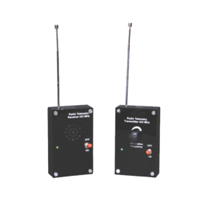
RF telemetry system consists of a radio frequency transmitter and matching radio frequency receiver both operating at 433 MHz. The system is designed for the radio frequency transmission and reception. The radio frequency transmitter sends out a variable audio signal and the radio frequency receiver with built in loud speaker receives the signal. The system enables the teachers to demonstrate a variety of wave phenomenon. The system also enables the properties of the radio communications to be investigated and compared with those of visible light and other wave motions such as audible sound and water waves etc. For the operation of the system, a 9 V PP3 battery is required.
Seven Segment LED Display Circuit
A common anode seven segment module is fitted on a board with 8 bit dip switch to control the each segment of seven segment LED display. The inputs A-D of a display driver are connected to the binary coded decimal (BCD) outputs from a decade counter. A network of logic gates inside the display driver makes its outputs a-g become high or low as appropriate to light the required segments a-g of a seven segment display. A resistor is required in series with each segment to protect the LEDs
Signal Generator
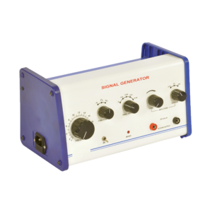
Audio frequency Generator is versatile instrument providing sine, square & triangular wave functions over a wide range from 2 220 KHz in decade ranges. The amplitude of the waveforms can be varied from 20 mV to 20 V peak to peak about zero level with the help of three step coarse control & fine control. The complete unit is enclosed in an attractive metal cabinet.
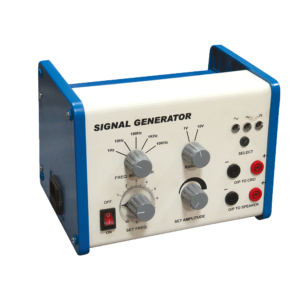
Signal Generator
1 Hz to 100 KHz in five decade ranges selected by rotary switch named as frequency Multiplier. Sine Triangular and Square waveforms selected by push switch with LED indication. Output signal is 0-3.5 V rms (10 V peak to peak) open circuit continuously control with uncalibrated amplitude control knob. Mains rocker switch with indicator Light. Signal Generator is versatile for general laboratory use; output signal is adjustable with the combination of Freq. multiplier and set frequency dial with a low level of distortion. Output Voltage is continuously variable with selector range 1V and 10V. There is two pair of output safety sockets. One for CRO output (experiment for amplification, filter etc.) and another pair of sockets to speaker to drive a speaker and to demonstrate the audio signal frequency range 20 Hz to 20 KHz.
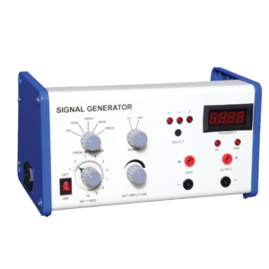
Signal Generator, Digital
This signal generator is a useful test instrument capable of generating multiple waveform and offers excellent waves shape, signal linearity, waveform symmetry and frequency range with selection of sine, triangular and square wave and amplitude variable 10 V peak to peak. 1 Hz to 100 kHz in five decade ranges selected by rotary switch named as frequency multiplier. Sine, triangular and square waveforms selected by push switch with LED indication. Output signal is 0 – 3.5 Vrms (10 V peak to peak) open circuit continuously control with uncalibrated amplitude control knob. Mains rocker switch with indicator Light. Signal Generator is versatile for general laboratory use; output signal is adjustable with the combination of frequency multiplier and set frequency dial with a low level of distortion. Set frequency is displayed on a 4 seven segment display. Output Voltage is continuously variable with selector range 1 V and 10 V.There is two pair of output safety sockets. One for CRO output (experiment for amplification, filter etc.) and another pair of sockets to speaker to drive a speaker and to demonstrate the audio signal frequency range 20 Hz to 20 KHz.

