Error: Contact form not found.
DC Network Analyzer
Specification
• Here we provide the bi-polar Transmission Line. • Simulated long, medium & short distribution lines selectable by patching in various length of DC Transmission line • Two no of bi-polar DC generator sources with ON/OFF control and voltage regulator potentiometer. - Two wire or Three wire Transmission Line operated in +12V DC - Each DC generator are independently control by potentiometer. • 2 digital voltmeters and ammeters provided in the input side and 2 digital volt meters and ammeters are provided in the output side • of transmission line to read the input & output parameters of transmission line. • One no of microcontroller based measuring system provide to read the input and output parameters. • 4 nos of digital ammeters provided to read the load current • 4 nos of resistive load and 4 nos of lamp loads are provided to load the transmission line.Electro Mechanical Type Over Voltage Relay Study Trainer
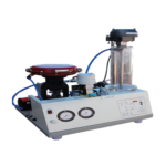
This test set-up consists of a. Electromechanical over voltage-relay. b. Relay test setup with meter.
Electromechanical over voltage-relay
• One electromechanical type over voltage relay - Make: Megawin - Voltage setting multiplier (121V, 132, 143, 154, 165, 176, 187V) - Time setting multiplier. - One “NO” contact @ 220V, 10Amp rating. - One “NC” contact @ 220V, 10Amp rating. b. Relay test setup with meter • One 0-300V, 1AMP variable AC source provided for relay coil. • One auto transformer provided for AC voltage adjustment. • One illuminated rocker switch provided for power ON/OFF. • One digital voltmeter used to indicate applied voltage. • One digital timer provided for relay tripping time measurement. • One automatic relay tripping time measurement circuit. • One start/stop push-to on switch provided for time measurement circuit. • One reset switch provided for timer reset.Microcontroller Based Differential Relay
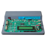
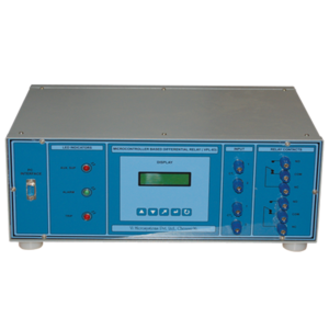
This test set-up consists of a. Microcontroller based differential relay. b. 300VA transformer set-up
Specification
• One PIC Microcontroller used as processor to read all current, (PY, SY) & activation of relay function • One LCD to indicate, - Set value, All currents - Set time, DMT/IDMT type - Relay tripping time. - Biased/Unbiased type status • Four numbers of key used - To select IDMT/DMT type or biased un-biased type - Set current value adjustment - Set time adjustment - Reset function • Six 5A CT used to sense primary and secondary current. • One 12V TPTT auxiliary relay used for contactor operation. • Specification: - Current input : 0-5Amp - Voltage input : 0-230V - Number of contact : Three number No contact @ 220V, 10Amp rating. - Auxiliary supply : 230VAC, 50Hz • PC interfacing facility power ON/OFF switch with indicator. • Make : VI MICRO • Model : VPL - 83AMicrocontroller Based Distance Impedance Relay Trainer
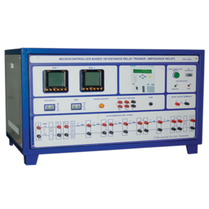
It consists of many components i. Transmission line module ii. Voltage and current signal conditioners iii.Distance Relay iv. Multifunction Meters
Transmission Line Module
• Total line length - 180Km • Modeled by RL - parameters • Current rating - max 5A • Voltage rating - max 250V ACVoltage and Current Signal Conditioners
• One no of 5A/5V current transformer is provided to read the relay current input • One no of 230V/9V potential transformer is provided to read the relay voltage inputDistance Relay
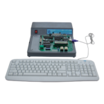
• One PIC microcontroller used as processor to activate the relay function • One LCD to indicate : - Impedance set value - Current & voltage value - Set time, Relay tripping time • Four numbers of keys are used • Parameters - Current input : 0-5Amps, Voltage input : 0-230V AC - Number of contact: One number of NO contact @ 220V, 10Amp rating - Auxillary supply : 230V AC, 50HzMultifunction Meter
• One MFM provided for measuring input side all parameters (V, I, PF, F, AVR, KW) • One MFM provided for measuring load side line parametersThree Phase Transmission Line Fault Analysis Trainer
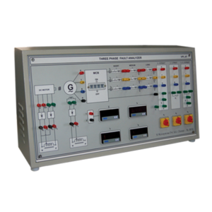
Three phase Transmission line fault Simulation Study Module

