Error: Contact form not found.
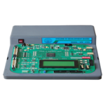
DDS RF Source and Network Analyzer
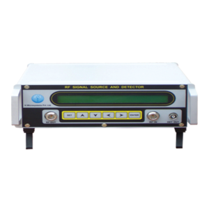
This unique instrument is RF source upto 1.7GHz with 10 to 400MHz in DDS mode of operation and few Network Analyzer capabilities.
Specification
• It works in two mode of operation. - 10 to 400MHz - DDS operation. - 400 to 1700MHz - PLL operation. • 10 to 1700MHz, RF signal generator. • RF Output Power: 10 to 400MHz, -2dBm, +/-3dB 400 to 1700MHz, -5dBm, +/-3dB. • Harmonics: 10 to 600MHz better than -15dBc 600 to 1700MHz better than -30dBc. • Attenuation: 5dBm, 10dBm, 20dBm, 30dBm. • Fixed and sweep RF signal source. • Direct digital synthesis (DDS) method based. • 100 KHz Channel step size. • AM/FM Modulation. • Automatic Level Control (ALC) incorporated so that, RF level output will be constant. • Graphics LCD display to plot Filter, Amplifier etc., characteristics.Microwave Integrated Circuit Trainer
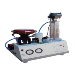
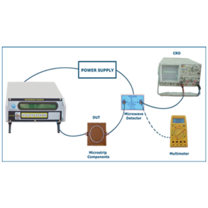
This trainer is used to study Microstrip components and its characteristics. A useful trainer to get hands on experience on Microstrip components and instrument. We offer Three solutions.
1GHz RF Source with Detector
• Frequency Range : 0.05 to 1GHz. • Resolution : 100KHz. • Automatic Level Control (ALC) RF Detecter& Directional coupler provided for many RF measurements. • Output Impedance : 50 Ohm.1GHz Micro Strip Component
• Ring Resonator. • 3dB Power divider. • Direction of Coupler.RF Signal Source with Detector
Specification
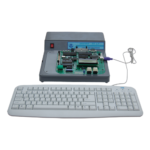
• 25 to 6000MHz RF synthesized signal generator. • Programmable attenuator 5, 10, 20, 30dBm up to 1.5GHz. • 40 x 2 LCD Display to display the frequency of the RF signal and RF signal level. • Output level : 0dBm +/2dB upto 1GHz, -5dBm, +/-2dB upto 3GHz, -10dBm, +/-3dB upto 6GHz. • Output impedance : 50 ohm. • One RF Power detector provided for 50 to 1000MHz frequency range and this output is measured • by an ADC and display on the LCD display. • 6 Keys keypad provided to select the desired frequency, attenuation level, Sweep mode. • Step size : 1MHz. • Connectors: - 2 Nos. of 'N' type connector for RF out and RF in. - One "BNC" type connector for RF detector output.Transmission Line Trainer
This trainer is designed for study of co-oxial cable characteristics like Impedance measurement, VSWR measurement etc., It is based, i) The latest technology of DDS Based RF source. ii) Directional coupler for VSWR Measurement. iii) TDR to measure the cable fault.

