Error: Contact form not found.
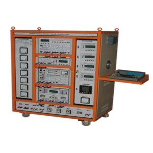
400W Smart Grid Experimental Setup
This consists of 2 Microgrid, one 400W& 200W of power generation connected to a main Power Grid with all the components needed to convert a traditional Grid to a Smart so that many experiments can be conducted on this “Smart Grid”. 3Φ, 1KW isolation transformer with power input from utility grid will act as main grid to which 2 Microgrid will be connected through synchronizing panel. Optionally a commercial 1KVA Grid Connected Solar Power Inverter can be added to this experimental setup. By adding 1KVA commercial solar inverter, when the experimental setup is not used by student, it could be used to generate power.
This Advanced Smart Grid Experimental Setup Consists of
• 2 Micro Grids, 400W& 200Wof Power Generation using Solar, Wind or Hybrid • An Isolation Transformer coupled to the utility grid, acts as main grid to this Setup • Commercial 1KVA Grid Connected Inverter with Solar Panel (Optional) • Optional Components for the 400W Smart Grid Setup • DSP/FPGA Controller for PE, SG, PS Applications • IoT Based Data Acquisition • Other Add onsMicro Grid - I (Solar/Wind Grid Connected 1Φ, 400W Smart Micro Grid)
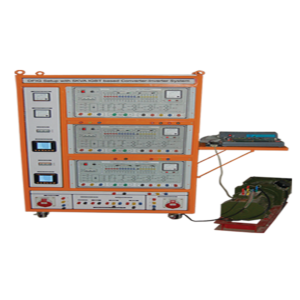
• Main Frame • 200W Solar PV Module with Stand • 200W Wind Turbine with Tower (Optional) • 30W Wind Turbine with Blower setup • 200W DC-DC Boost Converter for Solar • 200W DC-DC Boost Converter for Wind • 400W Hybrid DC-DC Buck-Boost Converter • Battery Bank • 400W Inverters • Bi-Directional Buck-Boost Converter for Battery Charging • DSP/FPGA Controller • Microcontroller based Protection Relays • Smart Energy Meter • Synchronizing Panel • Single Phase R Load & Lamp Load (200W) + (200W) • PLC with SCADA Software • 8 Channel, PC based Power Quality Analyzer (Optional)5KVA IGBT Based Converter Inverter System
DC Motor Specification
• Power : 3HP • Armature voltage : 220V DC • Field voltage : 220V DC • Speed : 1500 RPM • Make : Benn • Double side shaft extensionSlip Ring Motor
• Type : 3phase slip ring induction motor. • Power : 2KW • Stator voltage : Three phase 415V AC, 4A • Rotor voltage : Three phase 210V AC, 6A • Speed : 1410 RPM • Make : BenndsPIC 30F4011 based PWM Controller
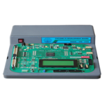
• Microchips’ dsPIC30F4011 16 bit digital signal controller operating at 20MIPS • On chip 48K Bytes flash program memory • On chip 1K Bytes data EEPROM • On chip 2K Bytes RAM • Four Compare/PWM output • Six PWM output for Motor control • One 3 channel Quadrature Encoder interface circuit/4 capture input • 9 Channels 10 bit ADC of 500Ksps conversion tune. • One RS232 Compatible serial port Opto isolated & terminated at 9 pin D male connector • 6 PWM outputs and two capture inputs and two compare outputs are terminated at 34pin FRC connector. • 4 Channels of DAC output & 5 channels of ADC inputs are terminated at 26 pin FRC connector • 16 x 2 alphanumeric LCD displaySmart Energy Meter
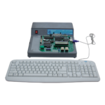
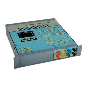
A Smart Energy Meter based on Analog Devices IC has been developed to build an Advanced Metering Infrastructure (AMI). The AMI system facilitates networking capability via GSM, ZigBee and ModBus. A Smart Energy Meter Development system has been developed by us, which consists of 1φ/3φ measurement section, a 32-bit ARM controller, wireless modules and powerful software. The student can completely understand the concept and usage of this trainer. This can be also used as one of the IOT server node.
Features
• 3 Phase energy readings displayed in the Graphics LCD • Simple design, Efficient and Highly Accurate • Easy connectivity for various loads • Keys to change the settings • Supports GSM, ZigBee and ModBus for networking • LPC2148 based processing board • 32/16 bit ARM7TDMI-S CPU with 60MHz maximum CPU clock • On board peripherals for extension • Graphics LCD interfaced to display the energy readings • Keys for various settings • Current Sensors and Voltage Sensors provided to measure 3 phase voltages and currents • Polyphase energy metering IC provides highly accurate energy measurement • Energy metering IC interfaced via I2C with Controller module • CC2530 Controller with maximum 32MHz CPU clock • High-speed and low-power 8051 CPU • 2.5GHz IEEE 802.15.4 compliant RF transceiver upto 250kbps data rate • UART Connectivity to interface with CPUSmart Grid Simulator
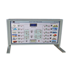
Smart Grid Simulator (VPST - SGS - 01) is a convenient solution for studying the basic Architecture and the Real-Time Operation of Smart Grid, Which consists of i) 8 types of Generation ii) Transmission Line iii) Six types of loads iv) Communication through LCD and PC.
Specification
• Six different generating station (Up to 10 MW) - Wind, Solar, Diesel, Bio-Gas, Fuel-Cell &UtilityGrid. • Two separate Transmission Lines (5MW Each) – TL-1, TL-2. • Six different power consumers (Up to 10 MW)– Gen.Industry, Emergency, Urban Area, Rural Area, Cement, Chemical Industry. • Six analog pot-meters for the power consumption control. • Graphics LCD & Keypad based configuration & monitoring of smart grid. • On board LCD & PC based GUI for easy understanding of the smart grid operation. • Automatic Smart Grid Control algorithm implemented for transmission line control, over current relay & automatic load sharing/adjustment in case of over loading.Solar Wind 3Φ, 2KW Smart Grid
This consists of 2 Microgrids of 2000W &1000W of power generation connected to a main Power Grid with all the components needed to convert a traditional Grid to a Smart so that many experiments can be conducted on this “Smart Grid”. A 3Φ 3KW isolation transformer with power input from utility grid will act as main grid to which 2 Microgrid will be connected through synchronizing panel. Optionally a commercial 3Φ, 2.5KVA Grid Commercial Solar Power Inverter can be added to this experimental setup. By adding 3Φ, 2.5KVA commercial solar inverter, when the experimental setup is not used by student, it may be used to generate power.
