Showing all 5 results

Flexible AC Transmission Systems

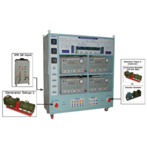
Three phase FACTS help the students to get insight of FACTS operation in Realtime by enhancing their understandings through various experiments. This module can be used to analyze the effect of shunt compensation (STATCOM- STATIC Compensator) series Compensation (SSSC - Static Synchronous Series Compensator) and Series - Shunt Compensation (UPFC - Unified Power Flow Controller) in the transmission line.

It consists of

• Generator Set-up (3Φ AC Source) • Simulated Transmission line • IGBT Based VSI Power Module • Series & Shunt Transformers with LC filter • RLC - Load setup • TMS320F2812 DSP Controller • Upgrade possible

Generator Set-up (3Φ AC Source)

• 3 phase Alternator DC Motor Drive setup 3Φ / 1KVA / 1500 RPM / Salient Pole type coupled with 2HP/220V DC shunt motor and with suitable drive from 1Φ AC input supply with • suitable speed control, sensor and digital speed indicator. • Digital controller with IGBT based DC voltage controller for DC motor Armature Voltage variation 0-200V DC/10A & Alternator field voltage variation with necessary instruments • /meters/indicators.

HVDC Transmission Line Simulator

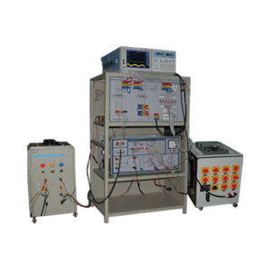
The HVDC Transmission due to its advantages, like long distance transmission, interconnect different power systems (like 50Hz and 60Hz), more energy transmits than AC, less losses, make it essential for the students to study & understand the operation of HVDC. Vi Micro have introduced a trainer for this purpose “HVDC Transmission Line Simulator”

HVDC Transmission Line System consists of

• Generating Station Module • Rectifier Station Module (SCR or IGBT Based) • Simulated HVDC Transmission Line Module • Inverter Station Module • Loading Module

Generating Station Module

• It consists of a 3Φ, 415V Variable AC source, 1.5 KVA step up transformer, a Multifunction Meter (To measure various electrical parameters of • Generating side or sending end) & a Miniature Circuit Breaker. • Earth Fault Relay is provided for protection against Earth Fault. • The module is covered with metallic enclosure and sticker represents the prime operation of the module. Safety power plug-sockets are provided.

Rectifier Station

• Two no’s of fully controlled SCR based bridge rectifiers provided to convert 3Φ AC to DC for HVDC transmission. • Two 6 Pulse SCR bridges connected in series • Can be configured as 12 Pulse Rectifier • A 3Φ, 1.5KVA transformer with (Y) primary and dual (Δ, Y) secondary are provided to reduce harmonics • The module is covered with metallic enclosure and sticker represents the prime operation of the module.

Shunt Active Filter Trainer

Specification

• FPGA Spartan 3A DSP board used for generating the PWM signals. • Three phase 3 level diode clamped inverter used as a Active filter. • SRF (or) Instantaneous PQ theory will be used to generating reference current. • PI control or fuzzy logic will be used to regulate the dc link capacitor voltage. • Reference DC link Voltage will be 250V. • Hall effect current transducers used to sense the source currents, load currents and compensation currents. • Hall effect voltage transducers used to sense the dc link voltage and source voltages. • Necessary source inductor and filter inductor provided. • Input source Line voltage -200V (Peak). • Input source Current -10A (Peak). • Power Rating -3KW. • Reactive power compensation can be provided. • 3KW linear and non-linear loads will be given. • User can modify source, filter inductance and external loads. • User can modify control algorithm. • Industrial type cabinet provided. • Before compensation source current THD will be greater than 26% • After compensation source current THD - 2.5 - 4% in 3 level inverter - 4 - 5% in 2 level inverter

Six Phase Power Analyzer

Specification

• 6 phase measurement @ 50Hz • 6 voltage inputs (250V AC max., 50Hz) & 6 AC current inputs (5A max) • Zero crossing output for both voltage and current waveforms • 6Nos of phase sensing circuits provided to measure the phase difference of 2 waveforms • Signal Conditioning for Torque & Speed (QEP, Proximity, Optical) • After Signal Conditioned, 6 voltage outputs, 6 current outputs, 12 zero crossing outputs & 6 phase sensing outputs are terminated at 34 pin and 26 pin FRC connectors • Power input through banana sockets • Housed in a sleek cabinet

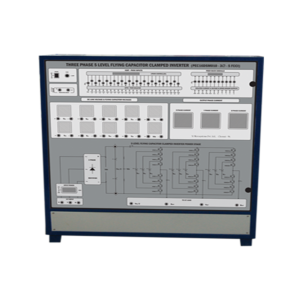
three-phase-flying-capacitor-5-level-inverter-power-module

Specification

• Power circuit consists of 24Nos, 1200V, 20A IGBT with proper heat sink and snubber circuit. • 18 Nos of flying capacitor provided • 6 Nos, Power Diode @ 500v is provided for power circuit • 24 Noshigh speedopto-isolator provided for IGBT PWM inverter. • 24 Nos IGBT gate driver IC provided for IGBT gate driving • 22 nos isolated +15v dc @ 0.5A capacity provided for control circuit • One no of 3phase diode bridge rectifier@1200V, 20A with capacitor provided for input AC-DC conversion • 3 no of Hall Effect current sensor provided for O/P current measurement & protection circuit • 1 no Hall Effect current sensor provided for DC current measurement • Two no FRC connector provided for IGBT PWM input & ADC interface • MCB protection for input power ON/OFF & protection • One no of restart switch and LED provided for protection circuit indication & reset the unit • One Number of analog DC voltmeter provided for DC voltage measurement. • One number of power ON/OFF switch provided. • 3 Phase outputs & 3 Phase inputs are terminated in the front panel. • Test points provided for PWM input and current sensors output