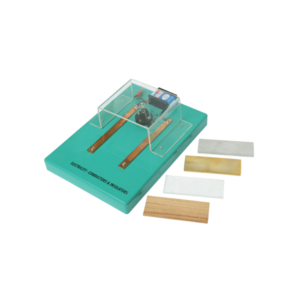
To distinguish between the conductors and insulators.
Kit contains five strips of different material (wood, acrylic, copper brass and aluminium), one lamp and one 9 V battery mounted on plastic base.
A simple kit for students to gain insight into field poles, armatures and switches, one mounting base, two coils of insulated wire , field pole, mounting bracket, two armature halves, one piece of insulating tubing, motor shaft, two commutator insulators, two bronze wire brushes, two shaft supports, four paper fasteners, a AA battery holder and 6 each of screws and nuts.
Requires one AA battery, not supplied, with assembly instructions.
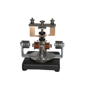
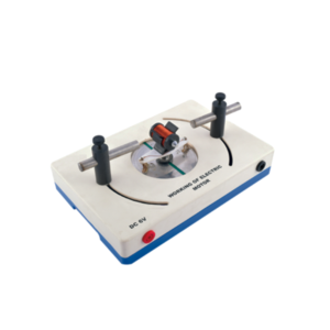
The motor consists of a two pole armature mounted between the ends of two bar magnets.
The armature has a two section commutator and a pair of slip-rings on its shaft and is so constructed that the wire cannot slip off the iron core.
The upper bearing and brushes for the commutator are mounted on a strong upright.
Separate brushes are provided for the commutator and for slip rings and each are connected to a terminal.
The magnets are held in position by thumb screws.
With this simple electric motor model students can investigate the relationship between voltage supplied to rotor and polarity / position of magnets.
On applying 6V DC to 4mm sockets, the rotor will begin to rotate across its vertical axis.
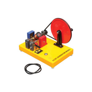
Generates both AC and DC.
When the two brushes of the generator are put in the two ends of the commutator, the output is an AC.
When the brushes are put in the middle of the commutator, the output is a DC.
Includes Instructions.
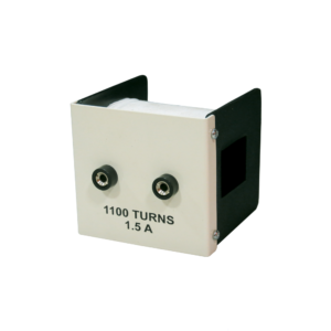
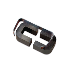
For use on double 'C' core, wound with 1,100 turns of 22 swg copper wire with a resistance of about 6 ohms and inductance of about 15 henries, size 100 x 60 x 55 mm approx.


Reviews
There are no reviews yet.