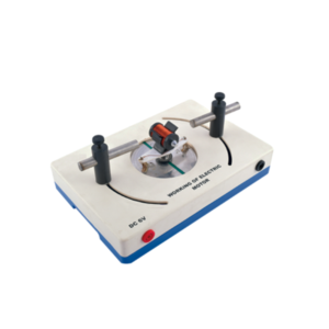
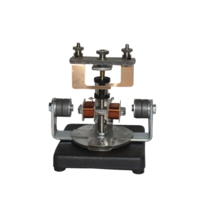
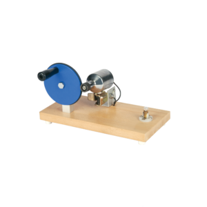
With this simple electric motor model students can investigate the relationship between voltage supplied to rotor and polarity / position of magnets.
On applying 6V DC to 4mm sockets, the rotor will begin to rotate across its vertical axis.
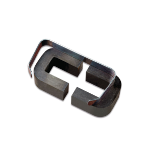
Apparatus is designed primarily for demonstration of the basic principles of transformers.
It consists of a laminated U-core with laminated I-core, both with 32 x 25 mm cross section to form a closed core of size 102 x 127 mm.
Heavy aluminium alloy stand with removable clamping rods, 2 pole pieces, each 65 x 30 x 25 mm with one end cone shaped, to accept support rod and shading ring.
Poles also have a hole drilled through lengthwise to take a light beam. 300 turns 600 turns 1200 turns 3600 turns 12000 turns
The motor consists of a two pole armature mounted between the ends of two bar magnets.
The armature has a two section commutator and a pair of slip-rings on its shaft and is so constructed that the wire cannot slip off the iron core.
The upper bearing and brushes for the commutator are mounted on a strong upright.
Separate brushes are provided for the commutator and for slip rings and each are connected to a terminal.
The magnets are held in position by thumb screws.
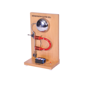
The large size of this battery operated apparatus allows students to better understand the operation of this basic circuit.
Works on 9 V Battery.
Includes Instructions.
On wooden stand.
Comprising 1 welding coil of 5 turns on former with insulated handle and short-circuiting pins,1 annular melting trough with insulated handle to show heating by induction,1 jumping ring which is thrown clear when primary current is started and a floating ring which remains freely suspended when primary current is flowing.
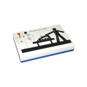
This apparatus is an effective demonstration of how the earth wire and fuse act together to protect both the user and the appliance.
When the appliance is connected correctly and the LEDs in the appliance will illuminate to show the appliance is working.
A fault is then demonstrated by swapping the live wire from inside the appliance to the case to show either the fuse melts (protecting the user and appliance) or in the case of no earth wire, the LEDs illuminate to indicate the passage of current through the person to ground.
The fuse is easily visible and can be seen to ‘blow’ when a fault occurs.The unit is supplied with 10 m of fuse wire and full instructions.
A 12 V DC power supply is required.
Connections are made via 4 mm shrouded sockets.


































Reviews
There are no reviews yet.