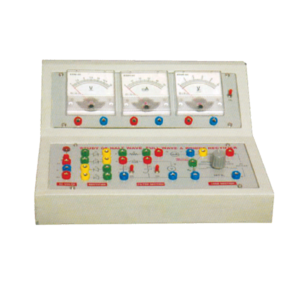
Objective : To study Efficiency and Ripple factor in case of Half wave, Full wave and Bridge rectifier on application of load and filters.
Features : Instrument comprises of AC Power Supply, 3 meters to measure Output Voltage, Output Current and ripple factor on electronic AC Voltmeter, 4 PN Junction Diodes, Filter Circuit kit, load Resistances selectable using bandswitch and all important connections points at 4mm Sockets.
Optional Acc : Digital AC millivoltmeter.
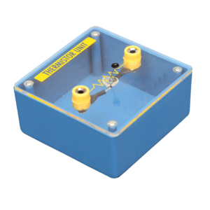
Mounted on transparent covered base for easy demonstration. Diagram and two sockets are provided for use with some circuit. Thermistor is mounted above the base to avoid the damage from heat.
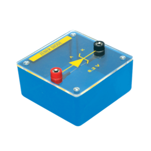
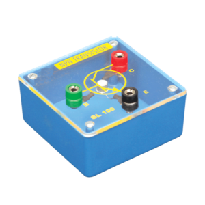
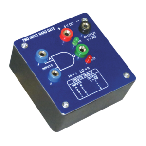
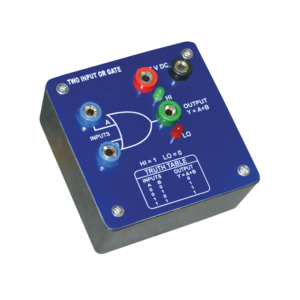
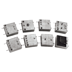
Each module is housed in a plastic box 90 x 90 x 30 mm and is provided with a circuit diagram on the panel. It has necessary input and output sockets. The socket stacking system allows addition of as many modules as desired, designed to work on 6V D. C.
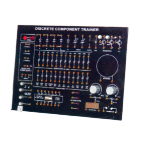
Trainer consisting of Power Supply of +5 V / ±12 V (each of 250 mA), Silicon, Germanium diodes, Zeners, PNP and NPN Transistors, FET, One speaker, 12 different values of carbon film resistances of ¼ W, ½ W and 1 W. 12 assorted values of capacitors from 100 pF to 1000 ?F, Integrated Circuit (IC) Base and IC 74LS00 1 No. each. LED, LDR, Photo diode, Solar Cell Logic Switches (4 No.) and LED Indicators (4 No.) etc., 2 mm Interconnection Leads -10 No. and Comprehensive User’s Manual
This panel is used to demonstrate the number systems such as binary, decimal and hexadecimal numbers. Toggle switches used to activate the displays showing the particular number entered. Input may be entered either as decimal or binary numbers with a toggle switch for mode selection. Decimal numbers are shown on a three digit seven segment LED display. 12 V / 2 A DC adaptor is required to operate it.
This Trainer Consist of :
1. Regulated power supply of ± 12 V / 250 mA.
2. Variable 0 to ±5 V / 250 mA.
3. Sine wave oscillation of 1 KHz.
4. Digital Voltmeter of 0-20 V DC, LCD display, 3 ½ Digit.
5. Functional diagram of IC 741 is printed with 2 mm sockets.
6. One extra 8 pin IC Base with 2 mm sockets.
7. Potentiometer of 10K Ohms.
8. Required Resistance and Capacitances mounted on board.
9. Interconnection Leads and Manual to perform 15 experiments on IC741 e.g. inverting, non-inverting, summing, difference, multiplier, differentiator, integrator etc.



































admin –
Good