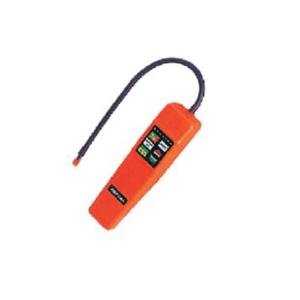
In old times refrigerant gas leakage was detected with the help of soap foam but with the help of refrigerant gas leak detector we can do the same job in more professional and reliable way.
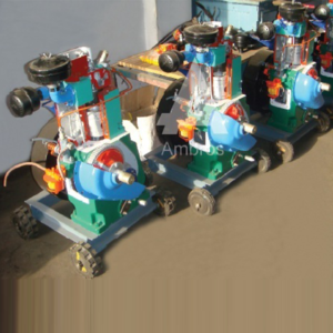
This model will be made out of original parts. The model will be suitably sectioned to demonstrate the internal construction details showing the minute information, and working of the same, the model will be suitably painted and mounted on a metal or wooden base & supplied with key card & very interesting literature regarding working of the same.
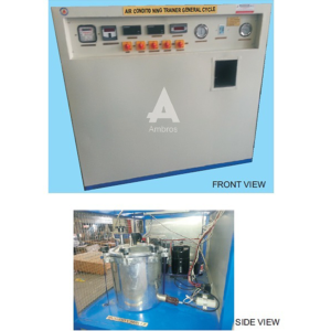
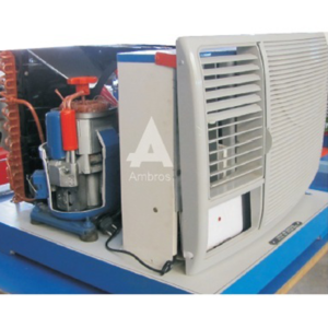
Window air conditioner is becoming now a day’s necessity. The unit demonstrates the application of window air conditioner & evaluation of its performance. It consists of a small room to which a small air conditioner is connected the room is provided with a transparent front cover with a heater inside to simulate heat load in the room. Various measurements are provided so that performance of system that is COP of system, actual & theoretical cooling capacity of system & power consumption of unit with different load conditions.
SPECIFICATIONS:
1.Compressor – Hermetically sealed, Kirloskar make, having the capacity of 1/10 ton of refrigeration using R-12 refrigerant to keep room temperature between 20 to 30 c.
2.Condenser – Finned tube type, with forced air flow over the tubes,
3.Capillary tube of matched length as expansion device.
4.Evaporator – Finned tube type with forced air flow,
5.Room – 0.6 X 0.7 X 0.7 m. height, provided with transparent front wall. A heater with input control is provided inside the room. Which simulates different load conditions.
6.Measurements and Controls
a) H.P. / L.P. Pressure gauges
b) Digital temperature indicator to measure the temperatures at various points.
c) Energy meters to measure input to compressor & heater.
d) High and low pressure cutout.
e) Thermostat to put off the compressor at set room temperature.
f) Necessary switch for electrical components.
SERVICES REQUIRED:
1.Floor area of 2m X 1 m.
2.230V, 15AC stabilized supply with earthing connection
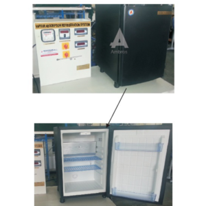
This type of refrigeration is usually used for domestic purposes only as it is complex in the construction and working. This type of refrigerator was developed in 1925 by Munters and Battzervan when they were studying at Royal Institute of Technology At Stockholm for their undergraduate course. This type of refrigerator was known as three fluid refrigeration system. The elimination of aqua pump from the absorption system with the complete absence of moving parts and work input. The main purpose of removing the pump was to make the machine noiseless. It uses refrigerant as a solvent s and an inlet gas for inlet of the system. The inert gas is continued to the lower side of system only by its system. It is possible to maintain the uniform pressure throughout the system and after sometime permitting the refrigerant to evaporator at low temperature corresponding to its partial pressure. In the high pressure side system (generator and condenser), there exists only the refrigerant which is subjected to total pressure of the system so that it is condensed by using normal cooling water as air as it is done in other system.
The strong aqua ammonia solution is heated in generator by the application of external heat source. The water vapor carried with ammonia vapor is removed in separate form as shown in figure. Then the dry ammonia vapor is passed into the condenser and it is condensed by using external cooling source. The liquid ammonia flows under gravity in the evaporator and it evaporates. The mixture of hydrogen and ammonia vapor is passed into the absorber and the weak solution from aqua ammonia from the separator is allowed to follow into the absorber, through tray this weak aqua ammonia solution comes into contact with hydrogen separated. This strong solution is further passed to the generator and it completes the cycle.
The Plant uses ice can system. The cans filled with fresh wafer are kept in a tank in which brine is circulated. The brine is cooled by the refrigerant, which in turn cools the water in can and ice formation takes place.
SPECIFICATIONS:
1.Compressor : Kirioskar make hermetically sealed compressor using R 12 Refrigerant.
2.Condenser : 4 row type air cooled.
3.Expansion Valve : 0.5 TR capacity.
4.Evaporator : 1/2″ O.D. copper tube – 75 feet long.
5.Filter – Drier : Silica gel filled – 3/8″ flare connections.
6.Main Tank : 600 mm X 375 mm
7.Total Ice Cane Capacity : 7 Kg
8.Ice Making Capacity : 7 Kg / 4 Hours.
9.Thermocol insulation : 6.5″
10.Brine Stirrer : Motor driven fan, 1 phase, 1/10 HP, 1440.
INSTRUMENTATION:
1.Temperature Indicator : Digital Type O300°c, with 1 °c least count, using Cr/Al thermocouples.
Accuracy 1 % of full reading. 2.Compressor Energy Meter : Single Phase, 10 – 20 Amp. Capacity.
3.Pressure Gauge:
a)0-21 Kg/cm2
b) -1 to 10.6 Kg/cm2
c) Both of 65 mm dial.
4.Digital Thermometer
CONTROLS :
1.HP/LP Cutout : Auto reset type.
2.Thermostat : Auto reset type.
A technical manual accompanies the unit.
SERVICES REQUIRED:
1.Floor Area – 2m. X 1.5m. X 1.5m. Height.
2.220 V., 15 Amp.Single Phase Stabilized power supply
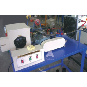
The unit consists of ducting fitted with various air conditioning components. Airflow is generated by an axial flow fan and in the airflow, heaters, cooling coil and steam humidifier connection is provided. Cooling circuit consists of a hermetic compressor; air cooled condenser, thermostatic expansion valve and evaporator (i.e. cooling coil). Measurements of various parameters Torn cooling cycle and heating cycle are provided and students can easily visualize and understand the basic principles of air conditioning.
SPECIFICATIONS:
1.Cooling circuits – It consists of:
a) Hermetic compressor, having the capacity of 2/3 ton of refrigeration (approx.) using R-22 refrigerant.
b) Rotameter for liquid refrigerant flow measurement.
c) Pressure gauges for high and low pressure.
d) Prescott (i.e. high and low pressure cut-out).
e) Thermometers for temperature measurement at various points In the cycle.
f) Energymeter for compressor input measurement.
g) Condensate measuring arrangement.
2.Heating Circuit – Air heaters with input control provided with energymeter for input measurement. Maximum heating capacity 1 Kw.
3.Steam generator and injector for humidification of air. All above components are connected to a duct of size 200mm. X 200mm. in which airflow is generated by axial flow fan.
4.Anemometer for measurement of air velocity, (range 0-15 m/sec. Following experiments can be conducted on the unit
a) Cooling of atmospheric air.
b) Heating of atmospheric air.
c) Humidification of atmospheric air.
d) Dehumidification and heating of atmospheric air.
(Cooling coil acts as dehumidifier at reduced airflow.)
SERVICES REQUIRED:
1.440 V, 15 A, 3 Phase supply with earthing connection.
2.Floor space area about 3 m. X 2 m.
This model will be made out of original parts. The model will be suitably sectioned to demonstrate the internal construction details showing the minute information, and working of the same, the model will be suitably painted and mounted on a metal or wooden base & supplied with key card & very interesting literature regarding working of the same.


Reviews
There are no reviews yet.