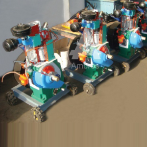
Heat Pump is a device to pump heat from one source to another. The heat obtained by heat pump is more than that could be obtained by direct electrical heating. The apparatus consists of refrigeration system with water cooled shell and coil type evaporator and condenser.
SPECIFICATIONS:
1.Compressor – Hermetically sealed compressor using R-12 refrigerant, having capacity 0.3 tons of refrigeration. Condensing pressure – max. 15 Kg/cm2 (Actual pressures will depend upon working conditions).
2.Condenser – Shell and coil type with continuous water flow arrangement.
3.Evaporator – Shell and coil type with continuous water flow arrangement.
4.Expansion Valve – Internally equalized thermostatic expansion valve.
5.Measurements –
a) Rotameter for condenser & evaporator water flow rate measurement.
b) Rotameter for liquid refrigerant flow measurement.
c) Pressure gauges for condensing and evaporating pressure – 2 Nos.
d) Thermometer for refrigeration cycle & water temp, measurement – 7
e) Wattmeter for compressor input measurement.
f) Ammeter for compressor current measurement.
6.Controls –
a) HP/LP cutout for compressor.
b) Overload protector for compressor.
c) Gate valve to control water flow rates.
d) Necessary switches and fuse.
A technical manual is accompanies the unit.
SERVICES REQUIRED:
1.Floor surface area – 2m, X 2m. X 1.5m. height.
2.220V. 15Amp. Single Phase Stabilized power supply.
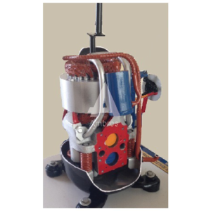
This model will be made out of original parts. The model will be suitably sectioned to demonstrate the internal construction details showing the minute information, and working of the same, the model will be suitably painted and mounted on a metal or wooden base & supplied with key card & very interesting literature regarding working of the same.
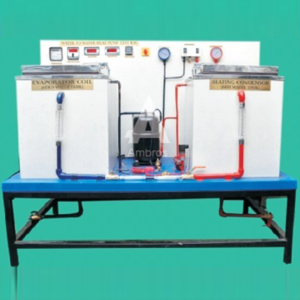
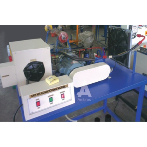
The unit consists of ducting fitted with various air conditioning components. Airflow is generated by an axial flow fan and in the airflow, heaters, cooling coil and steam humidifier connection is provided. Cooling circuit consists of a hermetic compressor; air cooled condenser, thermostatic expansion valve and evaporator (i.e. cooling coil). Measurements of various parameters Torn cooling cycle and heating cycle are provided and students can easily visualize and understand the basic principles of air conditioning.
SPECIFICATIONS:
1.Cooling circuits – It consists of:
a) Hermetic compressor, having the capacity of 2/3 ton of refrigeration (approx.) using R-22 refrigerant.
b) Rotameter for liquid refrigerant flow measurement.
c) Pressure gauges for high and low pressure.
d) Prescott (i.e. high and low pressure cut-out).
e) Thermometers for temperature measurement at various points In the cycle.
f) Energymeter for compressor input measurement.
g) Condensate measuring arrangement.
2.Heating Circuit – Air heaters with input control provided with energymeter for input measurement. Maximum heating capacity 1 Kw.
3.Steam generator and injector for humidification of air. All above components are connected to a duct of size 200mm. X 200mm. in which airflow is generated by axial flow fan.
4.Anemometer for measurement of air velocity, (range 0-15 m/sec. Following experiments can be conducted on the unit
a) Cooling of atmospheric air.
b) Heating of atmospheric air.
c) Humidification of atmospheric air.
d) Dehumidification and heating of atmospheric air.
(Cooling coil acts as dehumidifier at reduced airflow.)
SERVICES REQUIRED:
1.440 V, 15 A, 3 Phase supply with earthing connection.
2.Floor space area about 3 m. X 2 m.
This model will be made out of original parts. The model will be suitably sectioned to demonstrate the internal construction details showing the minute information, and working of the same, the model will be suitably painted and mounted on a metal or wooden base & supplied with key card & very interesting literature regarding working of the same.
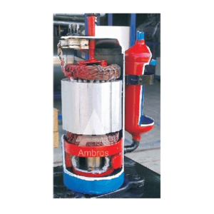
Actual Cut Section – Display Board (Set Of 30)
This actual cut section model is a set of thirty components used in refrigeration & air conditioning. With the help of this model students can understand the working parts of the components used in refrigeration & air conditioning. This model will be made out of original parts. The model will be suitably sectioned to demonstrate the internal construction details showing the minute information, and working of the same, the model will be suitably painted and mounted on a metal or wooden base & supplied with key card & very interesting literature regarding working of the same.
Desert Cooler Trainer works on the principle of evaporative cooling. It is used mostly in the dry hot regions; it consists of a fan which sucks the air from atmosphere through the pads which are used in desert coolers very frequently. The difference in DBT & WBT at inlet and outlet can be measured hence the RH from the charts. Also the amount of water evaporated can be calculated by knowing the water level difference in the reservoir.
SPECIFICATIONS:
1.Fan connected to 1/2 HP motor.
2.Air Cooler Pump to circulate water.
3.DBT & WBT Measuring Thermometer at inlet and outlet.
4.Orifice meter with manometer to measure the air flow.
A technical manual accompanies the unit.
SERVICES REQUIRED:
1.Floor Area – 1, X 1 m. X 1 -5m. Height.
2.220 V., 15 Amp. , Single Phase Stabilized power supply
This model will be made out of original parts. The model will be suitably sectioned to demonstrate the internal construction details showing the minute information, and working of the same, the model will be suitably painted and mounted on a metal or wooden base & supplied with key card & very interesting literature regarding working of the same.
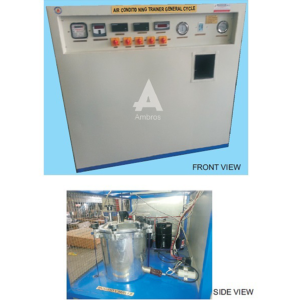
The unit consists of vapor compression refrigeration cycle provided with components normally used in refrigeration system so that student can get familiar with the components. Various measurement provided enable students to estimate the performance of the system.
SPECIFICATIONS:
1.Compressor- Hermetically sealed compressor, having capacity of 0.3 T.
2.Expansion Devices
a) Thermostatic Expansion Valve
b) Capillary tube.
3.Evaporator coil.
4.Controls:
a) Services Valve
b) Solenoid Valve
c) Filter-Drier for refrigerant
d) High/Low pressure cutout
e) Thermostat.
5.Measurements:
a) Thermometers (mercury in glass) – 4 Nos.
b) Pressure gauges for condensing and evaporating pressure.
c) Energymeter for compressor
d) Voltmeter and Ammeter for compressor.
e) Rotameter for liquid refrigerant flow measurement.
A technical manual is accompanies the unit.
SERVICES REQUIRED:
1.Floor surface area – 1m x 2m x 2m height.
2.220V, I5Amp, Single Phase Stabilized power supply


Reviews
There are no reviews yet.