Instrument is design to demonstrate the method to transmit signals via. Electromagnetic transmission. It is still used in radio system to transmit audio signal although it has lesser in popularity compared to FM (Frequency Modulation) due to its lower signal to noise ratio.
Technical Specification :-
1. I C based DC regulated Power Supply ±12 V / 500 mA.
2. Audio frequency 1 KHz / 0-2 Vpp for modulating signal 455 KHz / 2.5 Vpp approx. for Carrier Frequency.
Objective : To study Efficiency and Ripple factor in case of Half wave, Full wave and Bridge rectifier on application of load and filters.
Features : Instrument comprises of AC Power Supply, 3 meters to measure Output Voltage, Output Current and ripple factor on electronic AC Voltmeter, 4 PN Junction Diodes, Filter Circuit kit, load Resistances selectable using bandswitch and all important connections points at 4mm Sockets.
Optional Acc : Digital AC millivoltmeter.
A common anode seven segment module is fitted on a board with 8 bit dip switch to control the each segment of seven segment LED display. The inputs A-D of a display driver are connected to the binary coded decimal (BCD) outputs from a decade counter. A network of logic gates inside the display driver makes its outputs a-g become high or low as appropriate to light the required segments a-g of a seven segment display. A resistor is required in series with each segment to protect the LEDs
This Trainer Consist of :
1. Regulated power supply of ± 12 V / 250 mA.
2. Variable 0 to ±5 V / 250 mA.
3. Sine wave oscillation of 1 KHz.
4. Digital Voltmeter of 0-20 V DC, LCD display, 3 ½ Digit.
5. Functional diagram of IC 741 is printed with 2 mm sockets.
6. One extra 8 pin IC Base with 2 mm sockets.
7. Potentiometer of 10K Ohms.
8. Required Resistance and Capacitances mounted on board.
9. Interconnection Leads and Manual to perform 15 experiments on IC741 e.g. inverting, non-inverting, summing, difference, multiplier, differentiator, integrator etc.
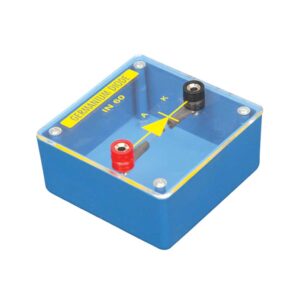
Diode mounted on transparent covered base for maximum visibility to students. Two four mm sockets one red and one black are provided for easy connections.
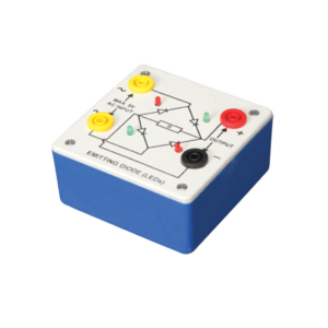
Bridge rectifier is designed with four LEDs internally arranged in bridge pattern fitted inside a plastic moulded case. Two LED’s are red and two LED’s are green. This device is used to demonstrate the functioning of a bridge rectifier, i.e., to convert alternating current (AC) into direct current (DC). Two yellow sockets are used for AC input. Two sockets, one red and one black, are used for DC output. For the easy understanding of the internal circuitry, the circuit diagram is printed on the box.




































Reviews
There are no reviews yet.