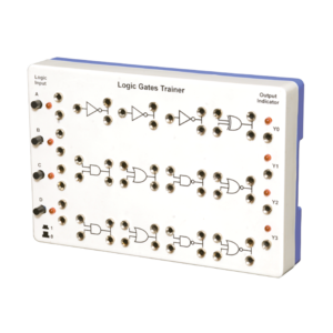
Logic Gates Trainer has been designed to study logic gates and applications. This trainer board is designed to verify the truth table of various logic functions, to prove De-Morgan’s theorem, Half adder and Full adder by using logic gates. The board is absolutely self-contained and requires no additional apparatus. 12 V / 1 A DC adaptor is required to operate it.
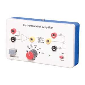
Instrumentation amplifier is a switched gain precision operation amplifier. This is used for precise and accurate, low noise differential signal acquisition. 4mm sockets are used for the input signal. It can be interfaced with a wide range of sensors. It can take small voltage changes from a sensor and make those changes large enough to be measured using CRO. It is not able to drive a low impedance load such as a loudspeaker or relay. The output can be read on CRO. Digital multimeter may also be used to read the output. With switched gain of 5 to 1000, it can handle signal inputs over a very wide range making it suitable for almost all applications.
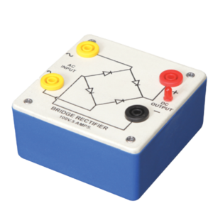
Bridge Rectifier is made of four diodes connected in a bridge circuit. It is housed in a plastic moulded box. This bridge rectifier converts alternating current (AC) into direct current (DC). It provides the same output polarity for either input polarity. All the electronic devices require direct current, so bridge rectifiers are used inside the power supplies of almost all electronic equipment. For the easy understanding of the internal circuitry, the circuit diagram is printed on the box.
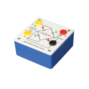
Bridge rectifier is designed with four LEDs internally arranged in bridge pattern fitted inside a plastic moulded case. Two LED’s are red and two LED’s are green. This device is used to demonstrate the functioning of a bridge rectifier, i.e., to convert alternating current (AC) into direct current (DC). Two yellow sockets are used for AC input. Two sockets, one red and one black, are used for DC output. For the easy understanding of the internal circuitry, the circuit diagram is printed on the box.
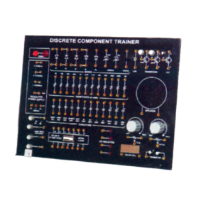
Trainer consisting of Power Supply of +5 V / ±12 V (each of 250 mA), Silicon, Germanium diodes, Zeners, PNP and NPN Transistors, FET, One speaker, 12 different values of carbon film resistances of ¼ W, ½ W and 1 W. 12 assorted values of capacitors from 100 pF to 1000 ?F, Integrated Circuit (IC) Base and IC 74LS00 1 No. each. LED, LDR, Photo diode, Solar Cell Logic Switches (4 No.) and LED Indicators (4 No.) etc., 2 mm Interconnection Leads -10 No. and Comprehensive User’s Manual
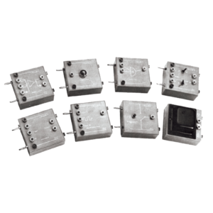
Each module is housed in a plastic box 90 x 90 x 30 mm and is provided with a circuit diagram on the panel. It has necessary input and output sockets. The socket stacking system allows addition of as many modules as desired, designed to work on 6V D. C.
Lorem Ipsum is simply dummy text of the printing and typesetting industry. Lorem Ipsum has been the industry's standard dummy text ever since the 1500s, when an unknown printer took a galley of type and scrambled it to make a type specimen book. It has survived not only five centuries, but also the leap into electronic typesetting, remaining essentially unchanged. It was popularised in the 1960s with the release of Letraset sheets containing Lorem Ipsum passages, and more recently with desktop publishing software like Aldus PageMaker including versions of Lorem Ipsum.

































Reviews
There are no reviews yet.