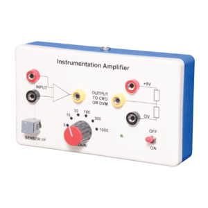
Instrumentation amplifier is a switched gain precision operation amplifier. This is used for precise and accurate, low noise differential signal acquisition. 4mm sockets are used for the input signal. It can be interfaced with a wide range of sensors. It can take small voltage changes from a sensor and make those changes large enough to be measured using CRO. It is not able to drive a low impedance load such as a loudspeaker or relay. The output can be read on CRO. Digital multimeter may also be used to read the output. With switched gain of 5 to 1000, it can handle signal inputs over a very wide range making it suitable for almost all applications.
A common anode seven segment module is fitted on a board with 8 bit dip switch to control the each segment of seven segment LED display. The inputs A-D of a display driver are connected to the binary coded decimal (BCD) outputs from a decade counter. A network of logic gates inside the display driver makes its outputs a-g become high or low as appropriate to light the required segments a-g of a seven segment display. A resistor is required in series with each segment to protect the LEDs
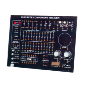
Trainer consisting of Power Supply of +5 V / ±12 V (each of 250 mA), Silicon, Germanium diodes, Zeners, PNP and NPN Transistors, FET, One speaker, 12 different values of carbon film resistances of ¼ W, ½ W and 1 W. 12 assorted values of capacitors from 100 pF to 1000 ?F, Integrated Circuit (IC) Base and IC 74LS00 1 No. each. LED, LDR, Photo diode, Solar Cell Logic Switches (4 No.) and LED Indicators (4 No.) etc., 2 mm Interconnection Leads -10 No. and Comprehensive User’s Manual
Objective : To plot Frequency Vs. Current Characteristics of LCR circuit when connected in series or in parallel.
Features : Instrument comprises of 3 Resistances, 3 Capacitors and 1 Inductance connected inside and connections brought out at Sockets. 2 AC moving coil meters to measure voltage and current.
Optional Acc. : Audio Frequency Function Generator



































Reviews
There are no reviews yet.