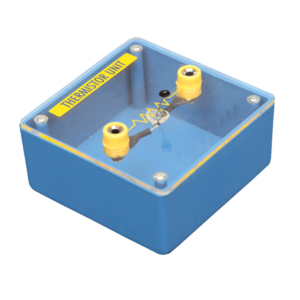
Mounted on transparent covered base for easy demonstration. Diagram and two sockets are provided for use with some circuit. Thermistor is mounted above the base to avoid the damage from heat.
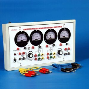
This Trainer Consist of :
1. Regulated power supply of ± 12 V / 250 mA.
2. Variable 0 to ±5 V / 250 mA.
3. Sine wave oscillation of 1 KHz.
4. Digital Voltmeter of 0-20 V DC, LCD display, 3 ½ Digit.
5. Functional diagram of IC 741 is printed with 2 mm sockets.
6. One extra 8 pin IC Base with 2 mm sockets.
7. Potentiometer of 10K Ohms.
8. Required Resistance and Capacitances mounted on board.
9. Interconnection Leads and Manual to perform 15 experiments on IC741 e.g. inverting, non-inverting, summing, difference, multiplier, differentiator, integrator etc.
Lorem Ipsum is simply dummy text of the printing and typesetting industry. Lorem Ipsum has been the industry's standard dummy text ever since the 1500s, when an unknown printer took a galley of type and scrambled it to make a type specimen book. It has survived not only five centuries, but also the leap into electronic typesetting, remaining essentially unchanged. It was popularised in the 1960s with the release of Letraset sheets containing Lorem Ipsum passages, and more recently with desktop publishing software like Aldus PageMaker including versions of Lorem Ipsum.
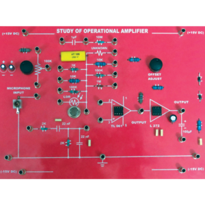
To demonstrate the function of operational amplifier using TL081 and L272 with discrete components different value of resistors, capacitor. Input can be applied from microphone, LDR. Offset null control is also provided. Output can be fed through the power amplifier into a loudspeaker.
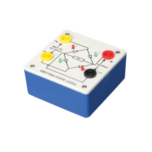
Bridge rectifier is designed with four LEDs internally arranged in bridge pattern fitted inside a plastic moulded case. Two LED’s are red and two LED’s are green. This device is used to demonstrate the functioning of a bridge rectifier, i.e., to convert alternating current (AC) into direct current (DC). Two yellow sockets are used for AC input. Two sockets, one red and one black, are used for DC output. For the easy understanding of the internal circuitry, the circuit diagram is printed on the box.



































Reviews
There are no reviews yet.