Logic Gates Trainer has been designed to study logic gates and applications. This trainer board is designed to verify the truth table of various logic functions, to prove De-Morgan’s theorem, Half adder and Full adder by using logic gates. The board is absolutely self-contained and requires no additional apparatus. 12 V / 1 A DC adaptor is required to operate it.
Objective : To study Efficiency and Ripple factor in case of Half wave, Full wave and Bridge rectifier on application of load and filters.
Features : Instrument comprises of AC Power Supply, 3 meters to measure Output Voltage, Output Current and ripple factor on electronic AC Voltmeter, 4 PN Junction Diodes, Filter Circuit kit, load Resistances selectable using bandswitch and all important connections points at 4mm Sockets.
Optional Acc : Digital AC millivoltmeter.
Trainer consisting of Power Supply of +5 V / ±12 V (each of 250 mA), Silicon, Germanium diodes, Zeners, PNP and NPN Transistors, FET, One speaker, 12 different values of carbon film resistances of ¼ W, ½ W and 1 W. 12 assorted values of capacitors from 100 pF to 1000 ?F, Integrated Circuit (IC) Base and IC 74LS00 1 No. each. LED, LDR, Photo diode, Solar Cell Logic Switches (4 No.) and LED Indicators (4 No.) etc., 2 mm Interconnection Leads -10 No. and Comprehensive User’s Manual
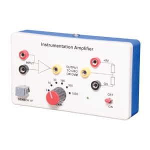
Instrumentation amplifier is a switched gain precision operation amplifier. This is used for precise and accurate, low noise differential signal acquisition. 4mm sockets are used for the input signal. It can be interfaced with a wide range of sensors. It can take small voltage changes from a sensor and make those changes large enough to be measured using CRO. It is not able to drive a low impedance load such as a loudspeaker or relay. The output can be read on CRO. Digital multimeter may also be used to read the output. With switched gain of 5 to 1000, it can handle signal inputs over a very wide range making it suitable for almost all applications.
This Trainer Consist of :
1. Regulated power supply of ± 12 V / 250 mA.
2. Variable 0 to ±5 V / 250 mA.
3. Sine wave oscillation of 1 KHz.
4. Digital Voltmeter of 0-20 V DC, LCD display, 3 ½ Digit.
5. Functional diagram of IC 741 is printed with 2 mm sockets.
6. One extra 8 pin IC Base with 2 mm sockets.
7. Potentiometer of 10K Ohms.
8. Required Resistance and Capacitances mounted on board.
9. Interconnection Leads and Manual to perform 15 experiments on IC741 e.g. inverting, non-inverting, summing, difference, multiplier, differentiator, integrator etc.


Reviews
There are no reviews yet.