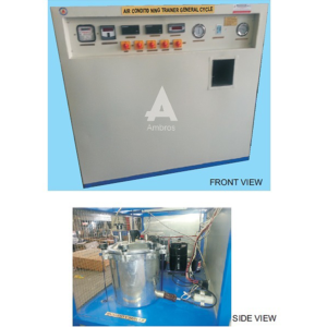
The unit consists of ducting fitted with various air conditioning components. Airflow is generated by an axial flow fan and in the airflow, heaters, cooling coil and steam humidifier connection is provided. Cooling circuit consists of a hermetic compressor; air cooled condenser, thermostatic expansion valve and evaporator (i.e. cooling coil). Measurements of various parameters Torn cooling cycle and heating cycle are provided and students can easily visualize and understand the basic principles of air conditioning.
SPECIFICATIONS:
1.Cooling circuits – It consists of:
a) Hermetic compressor, having the capacity of 2/3 ton of refrigeration (approx.) using R-22 refrigerant.
b) Rotameter for liquid refrigerant flow measurement.
c) Pressure gauges for high and low pressure.
d) Prescott (i.e. high and low pressure cut-out).
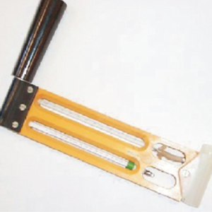
e) Thermometers for temperature measurement at various points In the cycle.
f) Energymeter for compressor input measurement.
g) Condensate measuring arrangement.
2.Heating Circuit – Air heaters with input control provided with energymeter for input measurement. Maximum heating capacity 1 Kw.
3.Steam generator and injector for humidification of air. All above components are connected to a duct of size 200mm. X 200mm. in which airflow is generated by axial flow fan.
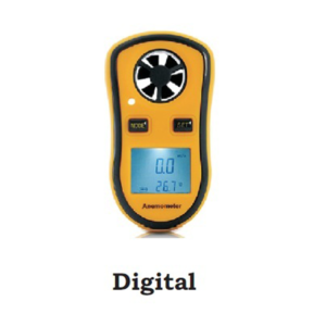
4.Anemometer for measurement of air velocity, (range 0-15 m/sec. Following experiments can be conducted on the unit
a) Cooling of atmospheric air.
b) Heating of atmospheric air.
c) Humidification of atmospheric air.
d) Dehumidification and heating of atmospheric air.
(Cooling coil acts as dehumidifier at reduced airflow.)
SERVICES REQUIRED:
1.440 V, 15 A, 3 Phase supply with earthing connection.
2.Floor space area about 3 m. X 2 m.
This apparatus is used to calculate the wind or air velocity. We can place the anemometer in front of air vent of a window air conditioner and record the air velocity.
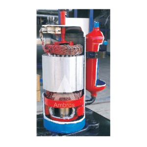
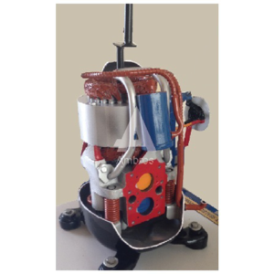
This model will be made out of original parts. The model will be suitably sectioned to demonstrate the internal construction details showing the minute information, and working of the same, the model will be suitably painted and mounted on a metal or wooden base & supplied with key card & very interesting literature regarding working of the same.
The unit enables students to study the various parameters affecting the performance of a domestic refrigerator. It consists of refrigeration cycle of domestic refrigerator, it consists a hermetically sealed compressor, air-cooled condenser, capillary tube and a natural convection type evaporator. The evaporator is fitted with a small heater to simulate different load conditions various measurements are provided so that power consumption, COP, theoretical and actual refrigerating effects refrigerant flow rate and effect of door opening on power consumption can be studied and also students can visualize automatic operation of unit using a thermostat.
SPECIFICATIONS:
1.Compressor – Hermetically sealed, Kirioskar make having capacity of approx. 1/25 ton of refrigeration.
2.Air – cooled condenser with natural convection airflow.
3.Capillary tube of matched length as expansion device.
4.Evaporator coil with an electric heater inside and adequate glass wool insulation on all side.
5.Measurement
a)Energymeter Tore compressor input power measurement.
b)Pressure gauge for condensing and evaporating pressure.
c)Flow meter for liquid refrigerant flow
d)Digital Temperature indicator for measurement of temperature
6.safety & Controls
a)High & low pressure cutout.
b)Thermostat.
c)Necessary Switches.
A technical manual accompanies the unit. Also, the unit is provided with an attractive and rust proof powder coating.
SERVICES REQUIRED:
1.Floor space of 2m x 1m.
2.230V AC stabilized supply with earthing connection
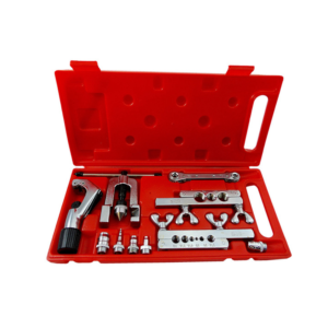
Refrigeration & Air Conditioning Tool Kit (Set Of 20)
This tool kit is a set of twenty tools used in refrigeration & air conditioning. With the help of this tool kit students can learn how to operate these tools & also understand there applications.
The Plant uses ice can system. The cans filled with fresh wafer are kept in a tank in which brine is circulated. The brine is cooled by the refrigerant, which in turn cools the water in can and ice formation takes place.
SPECIFICATIONS:
1.Compressor : Kirioskar make hermetically sealed compressor using R 12 Refrigerant.
2.Condenser : 4 row type air cooled.
3.Expansion Valve : 0.5 TR capacity.
4.Evaporator : 1/2″ O.D. copper tube – 75 feet long.
5.Filter – Drier : Silica gel filled – 3/8″ flare connections.
6.Main Tank : 600 mm X 375 mm
7.Total Ice Cane Capacity : 7 Kg
8.Ice Making Capacity : 7 Kg / 4 Hours.
9.Thermocol insulation : 6.5″
10.Brine Stirrer : Motor driven fan, 1 phase, 1/10 HP, 1440.
INSTRUMENTATION:
1.Temperature Indicator : Digital Type O300°c, with 1 °c least count, using Cr/Al thermocouples.
Accuracy 1 % of full reading. 2.Compressor Energy Meter : Single Phase, 10 – 20 Amp. Capacity.
3.Pressure Gauge:
a)0-21 Kg/cm2
b) -1 to 10.6 Kg/cm2
c) Both of 65 mm dial.
4.Digital Thermometer
CONTROLS :
1.HP/LP Cutout : Auto reset type.
2.Thermostat : Auto reset type.
A technical manual accompanies the unit.
SERVICES REQUIRED:
1.Floor Area – 2m. X 1.5m. X 1.5m. Height.
2.220 V., 15 Amp.Single Phase Stabilized power supply
This model will be made out of original parts. The model will be suitably sectioned to demonstrate the internal construction details showing the minute information, and working of the same, the model will be suitably painted and mounted on a metal or wooden base & supplied with key card & very interesting literature regarding working of the same.


Reviews
There are no reviews yet.