Error: Contact form not found.
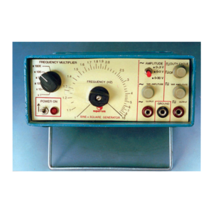
Sine / Square Oscillator 1 Hz – 1MHz
Wave Shapes : Sine and Square waves output 4 mm sockets.
Frequency Range : 1 Hz to 1 MHz using fine and coarse controls.
Accuracy : ± 5% on all ranges.
Amplitude for sine wave output : 30 Vpp.
Amplitude for Square wave output : 15 Vpp
Output Impedance for sine wave : Approx. 600 Ohms.
Output Impedance for square wave : Approx. 400 Ohms
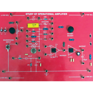
Study of Operation Amplifier
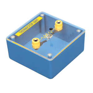
Thermistor Unit
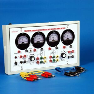
Transistor Char Appt
Lorem Ipsum is simply dummy text of the printing and typesetting industry. Lorem Ipsum has been the industry's standard dummy text ever since the 1500s, when an unknown printer took a galley of type and scrambled it to make a type specimen book. It has survived not only five centuries, but also the leap into electronic typesetting, remaining essentially unchanged. It was popularised in the 1960s with the release of Letraset sheets containing Lorem Ipsum passages, and more recently with desktop publishing software like Aldus PageMaker including versions of Lorem Ipsum.
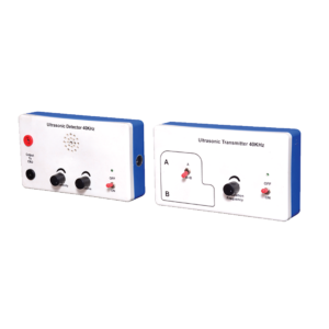
Ultrasonic Transmitter And Receiver Set
This apparatus consists of a self-contained transmitter and receiver operating in the 40 kHz region. The transmitted wave is modulated at a user controlled variable frequency of about 2 kHz and this is detected by the receiver which amplifies the signal and drives a miniature integral loudspeaker. Both transmitter and receiver are contained in separate plastic enclosures measuring 175 x 100 x 40 mm which contain all the electronics and the 9 V batteries. The receiver has front panel 4mm sockets so that the output can be monitored on an oscilloscope for more quantitative measurements. The system is ideal for demonstrating sound waves above the hearing threshold and reflection properties associated with sonar etc. A special feature is the second transducer on the transmitter which can be switched on when required to produce two coherent sources. By moving the receiver along a line parallel to the two sources interference patterns can be dramatically demonstrated simplifying the Young’s slits experiment or enabling it to be demonstrated using waves other than light. Complete with batteries, full instructions and suggestions for use.

